Graphics Reference
In-Depth Information
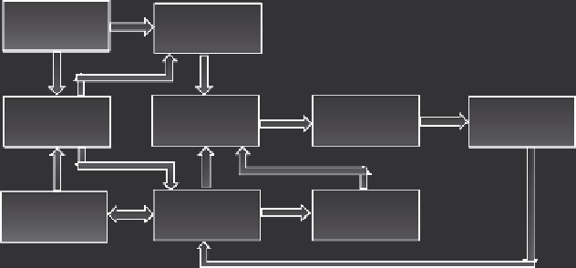
Per-vertex
operations
Vertex data
Per-fragment
operation
Display lists
Rasterisation
Framebuffer
Per-pixel
operations
Texture
assembly
Pixel data
FIGURE 2.1
Real-time 3D rendering pipeline.
•
For polygons to be rendered with visually correct features, each vertex
is associated with a set of attributes such as position (coordinates in 3D
space), colour, normal (perpendicular) vector from a surface, texture
coordinates (user-defined mapping onto the surface), and other factors.
•
Transformation to Global World Coordinates
•
To compose a scene in 3D space consisting of different objects, all cre-
ated 3D objects must be transformed into the same coordinate system.
•
These transformations modify only the relative positions of the vertices
and the normal. Visual attributes such as colour and texture coordinates
are not modified.
•
Transformation to 3D View Coordinate System
•
A viewpoint in 3D space is commonly cited as the “camera” location.
•
The geometry (vertex arrangement) from the 3D space is transformed
into the camera view coordinate system. Depending on the rendering
software, the common definition for this space is based on a right-
handed coordinate system with the camera at the origin pointing down
the negative z axis. The x axis is to the right and the y axis up. The
projection from 3D to 2D space is performed at this stage.
•
The depth information of any object can be obtained from the z coordi-
nate value at this stage.
•
The effect of virtual “lights” that create illumination properties in the
3D scene is computed at this stage. For example, a surface colour shad-
ing algorithm known as Gouraud shading will be computed at each
vertex of a 3D object using the light parameters, light position, normal
vectors, and the 3D object's texture or material properties.
•
The removal of polygonal surfaces not shown in the view due to occlu-
sion is known as “culling” and is performed at this stage as well.
•
Culling is related to the attributes of the camera view defined by a
virtual trapezoid volume known as the “view frustum” using six planes
(left, right, up, down, front, and back) as shown in Figure 2.2.
Search WWH ::

Custom Search