Environmental Engineering Reference
In-Depth Information
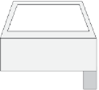
Figure 12.3 Example of an AHS vehicle and guideway ( from Reference 11 with
permission)
Figure 12.3 illustrates the AHS vehicle as discussed in References 9-11 and called
a PRISM, which stands for PRogram for Individual Sustainable Mobility.
Guideways, as shown in Figure 12.3, can be purpose-built narrow lanes located
in the median of present expressways, or these can be simply walled off lanes on
existing freeways that only NLVs such as PRISM can access. Once the PRISM
vehicle enters the guideway, all vehicle control becomes autonomous, the lane
consists of only two tyre strips that the vehicle system controller maintains head-
way on and locates the vehicle adjacent to a lane wall inductive power pick-up.
Power pick-up is shown in Figure 12.3 via a coaxial winding transformer (CWT),
designed to partially surround a primary power rail located on the guideway lane
wall at the vehicle's beltline height. The primary line would be a kilometres long
hairpin cable, rigidly supported on the lane wall and partially shielded to limit
exposure. This primary cable would need to operate at high voltage and high fre-
quency such as 5-50 kHz in order to transfer sufficient power to the vehicle to
maintain cruise speed of up to 95 mph intra-city and
>
150 mph inter-city.
Figure 12.4 shows in somewhat more detail the vehicle located on the guideway
and obtaining its propulsion power from the utility via the CWT rather than car-
rying large amounts on-board electrical energy storage.
P
RIS
M
Insulated power
distribution rod
One-turn
secondary
with iron backing
Guideway-mounted supply
Halbach
magnet
array
Shield
Car-mounted pickup
Figure 12.4 Inductive power transfer to PRISM vehicle on guideway and CWT
schematic ( from Reference 11 with permission)