Environmental Engineering Reference
In-Depth Information
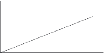
U
c
1
(
t
)
+
U
c
1
C
1
i
(
t
)
U
c
1
U
c2
(
t
)
+
U
c2
U
c2
C
2
C
1
C
2
T
Time (s)
Figure 10.33 Origin of ultra-capacitor cell voltage mismatch
10.2.5.1 Dissipative cell equalization
Dissipative cell equalization techniques are generally low cost and easy to imple-
ment methods consisting of resistor networks or sharp knee Zener diodes.
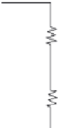
Figure 10.34 depicts a resistive balancing network in which the resistor values,
R
eq
,
are selected to ensure charge equalization during charge and discharge. The
individual time constants are selected so that the supply voltage becomes equally
distributed amongst the resistors within a reasonable equalization time.
+
U
c1
C
1
R
eq
i
(
t
)
+
U
c2
C
2
R
eq
Figure 10.34 Resistive cell balancing network
A second method of dissipative cell balancing is the use of sharp knee Zener
diodes in place of the equalization resistors as shown in Figure 10.35. Unlike a
resistor, the Zener diode will not conduct and shunt current from the cell until the cell
voltage reaches the Zener clamping level. With this, system performance is
improved, equalization losses are lower and overall module efficiency is higher than
with resistive equalization. When an individual cell starts to overvoltage the Zener
diode, voltage exceeds the clamp threshold and its dynamic conductance increases
sharply, shunting the cell charge and thereby preventing over voltage conditions.
Figure 10.35 illustrates a Zener diode equalization approach to cell balancing.
The major issue with either resistive or Zener diode approaches to cell balan-
cing is the high losses associated with achieving equalization. A further dis-
advantage of any dissipative balancing scheme is the relatively high current that
must be passed through the shunt network to realize equalization. If the capacitance
dispersion is
d
r
, then an amount of equalization current,
I
eq
, to be shunted away