Environmental Engineering Reference
In-Depth Information
B, T
B
s
B
B
r
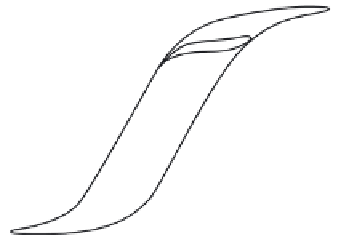
H
a
H
(A/m)
Figure 8.2 Magnetic hysteresis loops defined
Classical eddy current losses are calculated based on the lamination steel
electrical conductivity, geometry and magnetic characteristics. Equation (8.4)
illustrates the classical case and a more recent modification where the earlier
sinusoidal time varying induction is modelled as the summation of harmonics:
Classical
12
f
ð
T
s
d
2
B
2
P
e
¼
ð
t
Þ
dt
ð
8
:
4
Þ
Modern
P
e
¼
M
core
X
k
2
B
k
K
e
ð
B
Þð
kf
Þ
where
K
e
(
B
) is the material loss coefficient in W/kg.
To illustrate the components of core loss, suppose that two identical hybrid
M/Gs are fabricated (1) with cold-worked steel that has an electrical conductivity of
3.33
10
6
(
W
m)
1
and (2) with fully processed silicon steel having conductivity of
5.88
10
6
(
W
m)
1
, and both having thickness of 0.5 mm. The fully processed
laminations have higher conductivity and hence higher eddy current losses. The
cold-worked laminations will have higher hysteresis losses.
High efficiency M/Gs for hybrid propulsion will therefore be fabricated from
thin-lamination silicon steel. Some steel manufacturers have employed silicon
wafer processing techniques to the steel industry for the manufacture of motor
grade laminations. NKK steel was first to develop a novel graded silicon steel in
thin laminations having 15
m
m depth of 6.5% silicon content at both surfaces and a
core silicon content of 3% in their Super-E core line of 0.35 mm thick stock. This
particular formulation of silicon steel exhibits very low magnetostriction and very
low losses. However, the high silicon content does sacrifice some saturation
induction and also renders the laminations difficult to machine.