Environmental Engineering Reference
In-Depth Information
Matic
et al.
[24] describe a method of DTC that operates over constant torque
and in field weakening for both steady state and transient conditions. In their
method the objective is to achieve smooth and ripple free torque production of an
induction machine. In all DTC methods, two discrete equations govern the control
law for torque and flux as shown in (7.17):
m
d
m
¼
m
ð
t
k
Þ
ð
7
:
17
Þ
df
¼
f
f
ð
t
k
Þ
where
m
and f
are the commanded values of electromagnetic torque and stator
flux magnitude during switching interval
t
k
. Figure 7.16 illustrates the innovation
through which the present state is transitioned to the next state in the Matric
et al
.
[24] method of DTC whereby the present state of stator flux linkage, l
s
(
t
k
), is
transitioned to its commanded state, l
s
(
t
k
+1
).
State-
k
+1
l
s
(
t
k
+1
)
dl
s
State-
k
dq
l
s
(
t
k
)
q
(
t
k
)
d
-axis
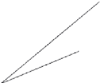
Figure 7.16 Stator flux transition by increment control under DTC (from
Reference 24)
Referring to Figure 7.16 the reference voltage applied to the voltage vector
selector is then given as the change due to flux increment plus the stator voltage
drop for the load conditions present during time interval,
t
k
:
dl
s
!
s
ð
t
k
þ
1
Þ¼
ð
t
k
þ
1
t
k
Þ
þ
R
s
!
ð
7
:
18
Þ
In the technique illustrated above, the machine currents are measured in the
conventional manner but flux and angle may be either sensed or estimated using a
flux and position observer (from measured voltages and currents).
Stefanovic and Miller [25] describe a DTC scheme for an induction generator
wherein flux and voltage are regulated. In this method flux is sensed through the
use of flux sensing coils in the stator and system bus voltage is measured and it
does not rely on current or rotor position measurements. Conversely, the method
can be applied wherein both flux sensing coils and current sensors are employed.
Figure 7.17 illustrates the case of DTC applied to an induction generator for the


