Environmental Engineering Reference
In-Depth Information
12.247449
20
I
qe
i
10
I
de
i
0
-6.123724
-10
0
100
200
300
400
i
0
359
(a)
9.999319
10
I
b
i
I
a
i
I
c
i
0
-9.999617
-10
0
50
100
150
200
250
300
350
400
0
359
i
(b)
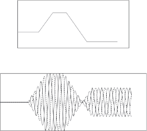
Figure 7.9 Dynamic response of FOC to motoring commands followed by
command to generate, I
de
= 0. (a) FOC ramp command to
motoring followed by ramp to generating in synchronous frame
and (b) response of M/G currents to ramp changes in M/G
torque command
frame currents do not carry much information beyond what the 3-phase currents do
in this chart, these will be omitted in the subsequent sets of charts. The effect in any
event is much the same as in Figure 7.8. Notice also that in Figure 7.9 the flux
command is held at zero. In Figure 7.10 the same scenario is presented but this time
for an increase in flux for the motoring action and a command to decrease flux
during generating.
I
de
commands for IM flux remain in the first quadrant since there
is no permanent magnet flux to attempt field weakening. If this were a synchronous
machine with permanent magnets, it would be appropriate to command negative
I
de
when generating at high speeds.
In Figure 7.10 the same scenario is repeated but with a more realistic
I
de
command that is representative of an IM M/G for a hybrid propulsion system.
In Figure 7.10 there is much more happening. First of all, not only is the torque
command given ramp changes into and out of motoring and then into generating,
but also the flux command is instructed to hold some initial value of flux then to
ramp flux up during motoring and gradually slew flux down as generating mode is