Environmental Engineering Reference
In-Depth Information
b
b
a
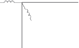
q
-axis
q
a
d
-axis
c
Figure 7.2 Schematic of the induction machine
The assumptions underlying these expressions are that the machine is balanced, the
magnetics are linear, airgap mmf is sinusoidal and the iron and stray losses are
neglected. It is important to use consistent rules of convention when dealing with
d-q
coordinate systems. In this work the commonly accepted and widespread
convention is that
X
qds
=(
X
qs
jX
ds
):
u
qs
¼
r
s
þ
p
l
qs
þ
w
e
l
ds
u
ds
¼
r
s
þ
p
l
ds
w
e
l
qs
u
qr
¼
0
¼
r
r
þ
p
l
qr
þð
w
e
w
r
Þ
l
dr
u
dr
¼
0
¼
r
r
þ
p
l
dr
ð
w
e
w
r
Þ
l
qr
l
qs
¼
L
s
i
qs
þ
L
m
i
qr
l
ds
¼
L
s
i
ds
þ
L
m
i
dr
l
qr
¼
L
m
i
qs
þ
L
r
i
qr
l
dr
¼
L
m
i
ds
þ
L
r
i
dr
ð
7
:
1
Þ
3
2
P
2
ð
l
qr
i
dr
l
dr
i
qr
Þ
m
em
¼
where w
e
is the excitation frequency (i.e. the electrical frequency), the operator
p
=
d
/
dt
, w
r
is the rotor mechanical angular speed and the rotor variables for electro-
magnetic torque,
m
em
, are used. Rotor variables for electromagnetic torque are
given in Figure 7.3:
n
o
3
2
P
2
I
m
i
qdr
l
qdr
m
em
¼
ð
7
:
2
Þ
where the asterisk symbol (*) represents conjugate operator.