Environmental Engineering Reference
In-Depth Information
PNGV's automotive integrated power
electronic module (AIPM) program:
Component
% total $
Control/comm/ps
13
Gate dr/modules/cable
30
Die cast/heatsink conn
33
Bus bars/curr sen/caps
24
100
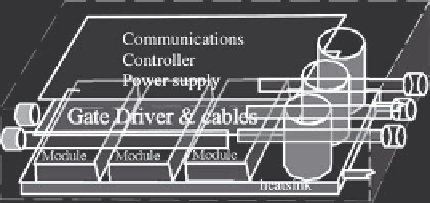
Figure 6.22 Power electronic inverter package for hybrid M/G applications
inverter component costs for a 300 V, 40 kW and a 42 V, 10 kW design. Note that
the system currents in both designs are nearly equal and the relative costs are
almost same, yet the total power throughputs are vastly different.
Future trends in IPEM design may expand on technology invented at the
General Electric and referred to as power overlay [18]. Power overlay is basically a
thin film multi-chip process for power modules. With this technique rather than
bonding chips to the top of a multi-layered substrate of interconnects, the chips are
embedded into the interconnected layers. Wire bonds are eliminated by use of
vertical interconnect access (vias) through the insulating layers connecting metallic
surface of the chip pads.
Investigations are on to increase the operating temperature of power electronic
and control electronic modules. Temperature ranges of interest are up to 200
C for
low band, from 200 to 300
C for medium band, and
>
300
C for high band.
The low band silicon-on-insulator (SOI) appears to show promise and some appli-
cations are in use today, but not for power. Power semiconductors are not adequate
for operation above 200
C; to exceed this temperature, devices with wider energy
Percent inverter cost breakout by subassembly
50
40 kW/300 V
10 kW/42 V
40
30
20
10
0
Figure 6.23 Cost cascade of 300 and 42 V power inverters