Environmental Engineering Reference
In-Depth Information
New bidirectional current drive
A
B
C
D
E
Stator
A
B
C
D
E
A
Rotor
(a)
Standard unidirectional current
Phase
A
A
Phase
B
B
Phase
C
C
D
Phase
D
E
Phase
E
Stator
Phase
-A
A
B
C
D
E
A
Rotor
(b)
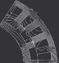
Figure 5.56 Unidirectional versus bidirectional current drive cases for VRM:
(a) unidirectional current drive and machine flux pattern and
(b) bidirectional current drive and flux pattern
It was also determined that bidirectional current would be advantageous since
machine torque would be higher and inverter switch current would be reduced. The
drawback was the need for twice as many active switches as shown in the sche-
matic in Figure 5.55. Figure 5.56 illustrates the differences between conventional
VRM unidirectional current drive and bidirectional current drive cases.
Figure 5.57 is a picture taken on a test dynamometer of the VRM starter-
alternator with an attached rotor position sensor. The machine is designed for stator
liquid cooling via the mounting housing shown.