Environmental Engineering Reference
In-Depth Information
The specific torque density of the electric machines shown in Figure 5.16 is the
most important metric of general applicability to hybrid propulsion. With the aid of
Reference 5 and prior developments in this topic, a short summary is made of the
specific torque density of these electric machines.
Table 5.5 Specific torque density figure of metric
Electric machine type
Specific torque
density (Nm/kg)
SPM - brushless ac, 180
current conduction
1.0
SPM - brushless dc, 120
current conduction
0.9-1.15
IM, asynchronous machine
0.7-1.0
IPM, interior permanent magnet machine
0.6-0.8
VRM, doubly salient reluctance machine
0.7-1.0
Table 5.5 lists the IM and VRM machines as having very comparable specific
torque. The range is included to offset the differences in power electronics require-
ments. In Reference 6 a detailed comparison of both machines was made when the
package volume was held constant for a hybrid propulsion application. In this work,
the power inverter was remote from the M/G and not included in the metric.
D 295.0 mm
f
295.0 mm
S/A performance attributes:
+
+
IM
VRM
Airgap
0.6
0.6
mm
Torque
285
187
Nm
At speed 500
500
rpm
I bus
102
75
A
dc
Induction machine
Variable reluctance machine
Torque density:
Electromagnetic mass:
9.24
7.06*
Nm/kg
Hub
3.6
3.6
kg
Rotor
8.35
4.6
kg
Torque constant:
Stator
Iron
2.8
2.5
Nm/A
8.6
8.4
kg
Polar inertia:
Copper 3.8
3.4
kg
kg m
2
Adaptor
6.5
6.5
kg
0.086
0.047
Total
30.85
26.5
kg
* Limited by inverter power switch rating.
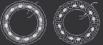
Figure 5.17 IM versus VRM when machine volume is held fixed
In Figure 5.17 it is instructive to note that for the same package dimensions,
stator OD and length, the VRM is somewhat lower in mass (26.5 kg versus 30.85 kg)
but that the IM developed higher specific torque because of limitations in the VRM
power electronics at that time. The IM and VRM have comparable torque per
ampere, but the VRM has much lower rotor inertia.