Environmental Engineering Reference
In-Depth Information
A useful analysis and graphical tool is the permeance coefficient,
P
c
, when any
PM is placed into some magnetic circuit. The permeance coefficient represents the
magnetic conductance of the circuit and is typically set to obtain as high a value of
airgap working flux in an electric machine as possible (i.e. minimal physical gaps).
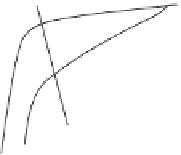
Figure 5.5 illustrates the second quadrant characteristics of a typical RE magnet in
both intrinsic and normal magnetization.
In Figure 5.5 the normal curve (5.2) and the intrinsic curve (5.3) traverse the
B-H
second quadrant from the remanence flux density,
B
r
, to coercive force,
H
c
,
and intrinsic coercive force,
H
ci
, respectively. A particular magnetic circuit design
determines the permeance coefficient at the static condition. When excitation cur-
rent is applied to an electric machine stator or armature, a demagnetization field is
impressed across the magnet, and if this field is sufficient to push the permeance
coefficient (i.e. load line) across the knee of the curve, there will be permanent
demagnetization. Figure 5.5 illustrates the case of normal operation at some ele-
vated temperature where the knee of the normal curve has moved up into the sec-
ond quadrant. Since operation is along the recoil line,
m
r
, of the normal curve, the
magnetic circuit remains intact over its useful operating life. However, in the case
of abnormal currents or faults, the PM may become demagnetized sufficiently to
render the machine unuseable.
(
r
c
+ 1)
r
c
B
B
r
B
m
=
B
g
r
c
m
r
B
d
H
ci
H
c
H
d
H
m
O
∑
I
arm
L
m
Figure 5.5 RE permanent magnet characteristics
An example will suffice to illustrate these points. In the following example, a
simple numerical calculation is performed in Excel, where the spacial and temporal
characteristics of an electric machine are approximated by columns and rows,
respectively. The column headings represent phase windings in a 3-phase brushless
dc machine of the type to be considered in the following section and the rows
represent a particular time point of the 3-phase currents. These currents are tem-
porarily displaced by 120 electrical degrees. The machine itself is assumed to be a
Q
¼
12 slots,
m
¼
3 phases,
P
¼
4 poles and
q
¼
1 SPP.
Example 2:
In this example, the brushless dc motor (BDCM) is assumed to be
excited by 80 A of armature current into phase coils of 80t (80 turns) each. The
SPM rotor consists of four poles, of which only two are highlighted in this example.
The convention here is that a positive clocked winding, such as phase A, is noted by