Environmental Engineering Reference
In-Depth Information
R
d
Power electronics
R
i
V
f
,
I
f
V
b
T
w
Transmission
Driveline
Control electronics
C'md's
Controller, comm.
gate drives, pwr supply
(a)
5
5
0
5
5
0
0.001
0.002
0.003
0.004
0.005
x
5
10
3
0
G(x)
f
b
(x)
(b)
1
1.2
0
-1.2
-1
0
0.001
0.002
0.003
0.004
0.005
5
10
3
0
x
f
s
(x)
(c)
1
0.8
I
a
(x)
0
-0.8
-1
0
0.001
0.002
0.003
0.004
0.005
5
10
3
0
x
(d )
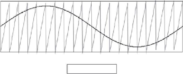
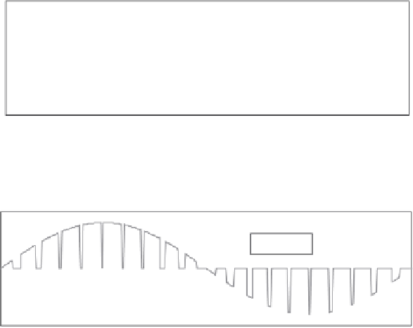
Figure 4.27 Power inverter PWM. (a) Inverter schematic for hybrid ISA system,
(b) inverter controller ramp comparison modulator, (c) digital control
waveforms for inverter phase A and (d) hybrid M/G phase A switch current