Environmental Engineering Reference
In-Depth Information
Step 3
. Validation of the combination ESS with selected energy management
strategies (EMS). In this case study only the dynamic set point SOC method
will be applied. Higher featured EMS such as Fourier transform and filtered
approaches that apportion ultra-capacitor power and battery power according
to vehicle
P
(
V
) frequency content are too complex for the intent of this study.
●
4.2.1 Step 1
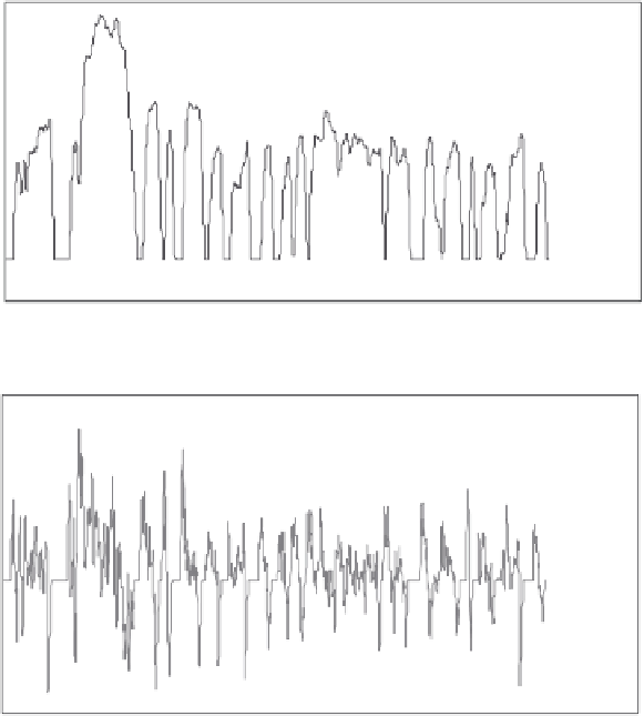
Parameters listed in Table 1 are input into an Excel spreadsheet and simulated over
a standard UDDS cycle [6]. In this case, the total vehicle mass consists of the glider
mass (ICE deleted-mass shown in Table 1 in parenthesis), the battery pack mass
and one standard passenger (mass ~75.5 kg). The total vehicle mass is therefore
1,299 kg and this value is input to the simulator along with all the parameters on the
right-hand side of Table 1. The vehicle level simulation calculates total tractive
effort (
N
) and fully accounts for aerodynamic resistance, rolling resistance and
inertial mass. From this the power profile is compiled (Figure 4.9).
60.00
50.00
40.00
30.00
20.00
10.00
0.00
0
.0
0
200.00
400.00
600.00
800.00
1,000.00
1,200.00
1,400.00
1,600.00
-10.00
(a)
Time (s)
35,000
25,000
15,000
5,000
0
200
400
600
800
1,000
1,200
1,400
1,600
-5,000
-15,000
-25,000
(b)
Time (s)
Figure 4.9 Simulation of tractive power,
P
(
V
) for Miata BEV: (a) urban
dynamometer drive cycle (UDDS) and (b) vehicle
P
(
V
) data file from
simulation