Environmental Engineering Reference
In-Depth Information
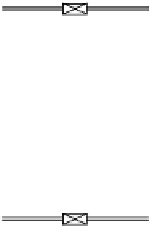
Interface
can be at
top or
bottom
Light-
phase
outlet
Heavy-
phase
inlet
Central shaft
Flat disk
Stator
Light-
phase
inlet
Heavy-phase
outlet
Figure 5.4
Agitated-tower extraction.
and the
y
-axis is the group
σ
ρ
c
0
.
2
a
v
ε
1
.
5
µ
c
ρ
,
V
s
,
d
=
where
V
s
,
c
,
superficial velocities of continuous and dispersed
phases, respectively, ft
/
h
µ
c
=
viscosity of continuous phase, lb
/
ft
·
h
σ
=
interfacial tension between phases, dyn
/
cm
ft
3
ρ
c
=
density of continuous phase, lb
/
ft
3
ρ
=
density difference between phases, lb
/
specific surface area of packing, ft
2
ft
3
a
v
=
/
ε
=
fraction voids or porosity of packed section.
It is important to note that neither group is dimensionless, so proper units must be used.
The
y
-axis can be estimated from physical properties and the corresponding
x
-axis
found. Then, the required dispersed or continuous solvent phase velocity can be found
as a function of a specified diluent flowrate. If the diluent is the dispersed phase, the
continuous solvent flowrate is found and likewise if the diluent is the continuous phase,
the dispersed solvent flowrate is determined. Obviously, there will be some variation
with column diameter and the best design is most easily determined with a spreadsheet


Search WWH ::

Custom Search