Hardware Reference
In-Depth Information
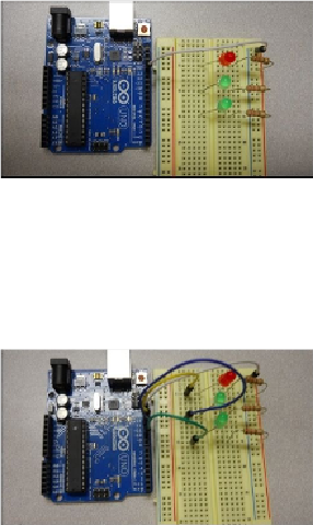
Finally, use jumper wires to connect the digital I/O pins 13, 12, and 11 to the holes on the
breadboard, as shown in the following image:
Now that the HW is configured correctly, you'll need to add code to activate the LEDs.