Biomedical Engineering Reference
In-Depth Information
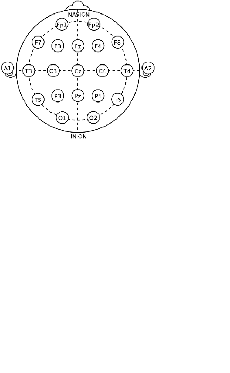
FIGURE 4.4:
Electrode locations of the International 10-20 system for EEG
recording.
ing from bioelectric activity of muscles, heart, or brain propagate all over the human
body the reference electrode has to be placed in proximity of the brain: on the ear-
lobe, nose, mastoid, chin, neck, or scalp center. In the bipolar setup (montage) each
channel registers the potential difference between two particular scalp electrodes.
Data recorded in a referential setup can be transformed into any bipolar montage,
for the sake of display or further processing. The “common average reference” mon-
tage is obtained by subtracting from each channel the average activity from all the
remaining derivations.
The Laplacian operator method is based on the fact that the Laplacian, calculated
as a second spatial derivative of a signal, offers information about vertical current
density and cancels common component due to volume conduction [Nunez, 1981,
Nunez and Pilgreen, 1991]. Hjorth transform [Hjorth, 1975] is an approximation of
the Laplacian operator method. The Hjorth transform references an electrode
E
0
to
its four closest neighbors:
J
∼
4
E
0
−
E
1
−
E
2
−
E
3
−
E
4
(4.1)
where
J
vertical current density at electrode 0 ,
E
i
—electric potential at electrode
i
.
There is no optimal reference recommended for all studies. For many applications
the Laplace operator method may be advised, but it requires a dense grid of elec-
trodes. For the methods where the correlations between channels are important, as
it is for MVAR, the reference electrode should be “neutral,” since the calculations


Search WWH ::

Custom Search