Image Processing Reference
In-Depth Information
better than deploying millions of less-capable, low-quality interlace-to-progressive con-
verters embedded inside receivers in the home.
5.6
Interlaced Field Rasters
Interlaced scanning was introduced in the 1930s as a way to reduce the number of lines
that must be transmitted to half of what was required for progressive scanning. This kind
of presentation requires that the odd- and even-numbered lines be presented independ-
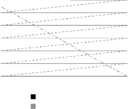
ently of one another. The presentation of interlaced lines is shown in Figure 5-2.
As the lines scan down the screen, the electron beam on a CRT display moves across
the tube face, painting horizontal lines as it goes. When the beam reaches the bottom of the
screen, it must go back to the top as quickly as possible to start the next downward pass.
This fly back accounts for about 8% of the scanning time, so you end up losing some of
the lines.
Note how a half line is necessary on each pass in order to properly interleave the
lines in the odd and even fields. It is tempting to just crop those two lines when com-
pressing the video. Very often the choices you make with a video processing operation will
have consequences (or knock-on effects) later in the workflow. In this case, removing just
a single line has a knock-on effect that potentially compromises the field dominance. Lines
must be removed in adjacent pairs. So those half lines are actually going to cost 4 lines of
image data. An alternative is to keep them, and work out how to fill the other half of each
line. A simple copy from an adjacent line would probably be the best solution.
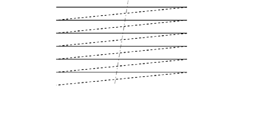
So the picture area is traversed twice, with one field being painted first and then on
the second pass, the other field is painted with the lines filling in the gaps. Figure 5-3
shows how an object is painted on the screen.
Visible lines
Horizontal flyback lines
Vertical flyback
Odd field
Even field
Figure 5-2
Interlaced scanning pattern.


Search WWH ::

Custom Search