Image Processing Reference
In-Depth Information
5.10.5
Synchronization
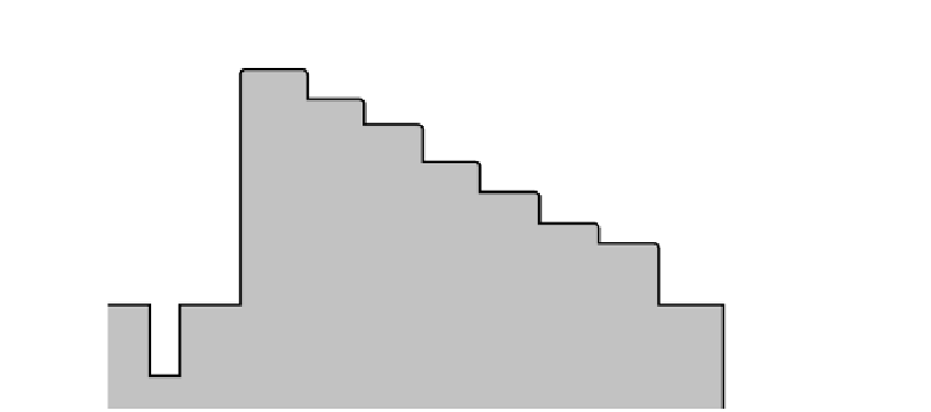
An example of a single line of analog video picture information is shown in Figure 5-25.
This is somewhat simplified and only shows the important aspects of the signal.
The dotted line indicates the area of interest to compressionists. We don't care about
levels that are higher or lower than this and any video to the left or right is not picture
information.
A synchronization pulse is visible at the left of the illustration. This is necessary for
aligning each successive scan line so that the picture is reconstructed correctly. Note also
that the only part that is interesting for compression purposes is the area occupied by gen-
uine picture information.
The vertical position of each line is determined by its location in the sequence of scan
lines making up the entire raster. Figure 5-26 shows a series of lines and how the vertical
synchronization is coded with some much longer sync pulses. This is greatly simplified as
the organization of sync pulses is very complex. Fortunately, the input circuits of the video
cards deal with all of this.
Only the visible scan lines containing meaningful picture information are relevant to
the compression process. However, it is important to find the right lines to compress. No
part of the synchronization signal is included in the compressed video output. If this part
of the picture is coded, it just wastes bit rate without conveying any useful picture infor-
mation. Cropping at the input of the encoder effectively deals with this.
5.10.6
Genlock
The term
genlock
is jargon that is contracted from generator locking. It describes the way
that multiple video services are synchronized together. It is also implemented on film
Sync pulse
'0' - Black level
Figure 5-25
Waveform for a single line of video.


Search WWH ::

Custom Search