Environmental Engineering Reference
In-Depth Information
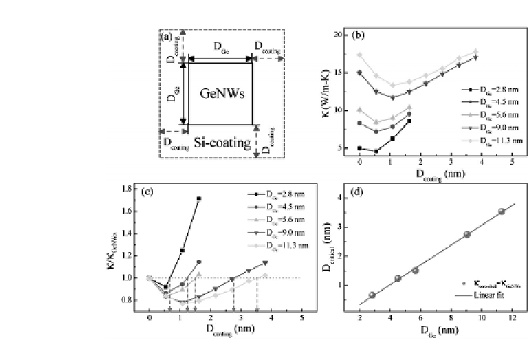
Figure 1.13
Coating configuration and thermal conductivity. (a) Cross-
section of GeNWs with Si-coating shell (dashed line). (b) Thermal
conductivity of GeNWs (
D
coating
=
0) and Ge/Si core-shell NWs (
D
coating
>
0)
for different
D
Ge
at room temperature. (c) Normalized thermal conductivity
versus coating thickness for different
D
Ge
. The dashed arrows point the
critical coating thickness when thermal conductivity of Ge/Si core-shell
NWs(
κ
GeNWs
).Thedashedlineisdrawn
to guide the eye. (d) The critical coating thickness
D
critical
versus cross-
sectional side length of GeNWs. The solid line draws the linear fitline.
κ
core
−
shell
)isequaltothatofGeNWs(
that for each GeNW, the coating of Si atomistic layers can reduce
the thermal conductivity. Further coating results in an increase of
thermal conductivity.
Increasingcoatingthicknesshastwooppositeeffectsonthermal
conductivity. On the one hand, the creation of core-shell structures
will induce the phonon resonance between the transverse and
longitudinal modes, thus offering a coherent mechanism to reduce
thermal conductivity. In Si-coated GeNW, atoms on the same cross-
section plane have different sound velocity in the longitudinal
direction. As a result, atoms near the interface are stretched, which
induces a strong coupling between the transverse and longitudinal
motions. Because of the spatial confinement on the cross-section