Environmental Engineering Reference
In-Depth Information
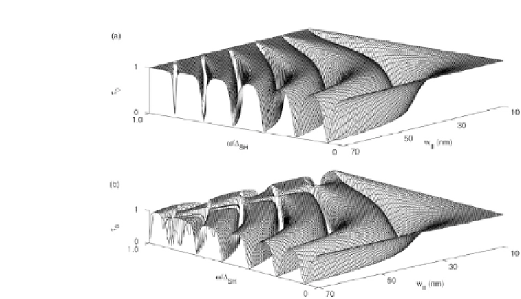
Figure 4.2
Transmission coe
cient
vs.
the transverse width
W
II
and the
frequency
ω/
SH
for the T-shaped quantum structure with
W
I
=
10 nm.
Here,
ω
m
+
1
−
ω
m
=
π
v
T
/
W
I
represents the splitting of the cutoff frequency
between the (
m
+
1) mode and the
m
mode [58]. (a)
b
=
10 nm; (b)
b
=
12 nm.
phonons stems from inhomogeneities in central region. Here, two
typicalofquantumstructureswithinhomogeneitiesareconsidered:
(i) T-shaped quantum waveguide; (ii) single structural defect such
as the defect being consisted of the void and clamped material
locatedinthemidsectionofnanowires.Somegeneralpropertiesare
revealed.
Forcase(i),itwasdemonstratedbyLi
et al.
[58]thathowseveral
lowest SH modes go through the T-shaped quantum structure.
Fig. 4.2 firstly shows the transmission coe
cient of the lowest
SH mode (zero mode) as a function of the incident frequency
and the transverse width
W
II
. It is seen that the zero mode with
the cutoff frequency
ω
=
0 can propagate through such the
structure, which is substantially different from the case for electron
transport. This is due to the fact that the acoustic phonon satisfies
the stress-free boundary condition, while the electron satisfies the
hard wall boundary condition. When
0, all the transmission
coe
cient approaches unity, which is consistent with that for
ω
→