Geoscience Reference
In-Depth Information
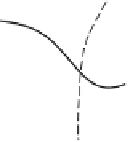
Fig. 12.18 Example of a tank arrangement used by Sugawara
and Maruyama (1956) to accommodate spatial
variability of the input over the catchment area, to
derive the unit response
u
=
u
(
t
).
α
1
α
α
2
3
α
1
δ
(t)
α
2
δ
(t)
α
3
δ
(t)
u(t)
α
1
δ
by
(
t
), one finds that the unit response of the first tank,
u
1
(
t
), is Equation (12.28)
multiplied by
α
1
. Similarly, the unit response from the second tank can be calculated
by routing the output from the first tank, i.e.
u
1
(
t
), plus the instantaneous rainfall on the
second subarea, i.e.
α
2
δ
(
t
), through the tank representing this second subarea,
)
exp[
t
α
1
exp(
−
τ/
K
)
−
(
t
−
τ
)
/
K
]
u
2
(
t
)
=
+
α
2
δ
(
τ
d
τ
K
K
0
or
(12.36)
K
+
α
2
In the same way, one can show that the outflow from the third tank, resulting from an
instantaneous input over the entire area, which is the unit response of the catchment, is
given by
exp(
−
t
/
K
)
t
u
2
(
t
)
=
α
1
K
t
K
2
exp(
−
t
/
K
)
α
1
2
t
K
+
α
3
u
(
t
)
=
u
3
(
t
)
=
+
α
2
(12.37)
K
In a similar approach, Nash (1957) assumed that the transformation of catchment
input into streamflow output is equivalent with a succession of routings through a series
of
n
linear storage elements; thus, the input enters the first tank and is then successively
routed through the second, the third, and so on (see Figure 12.19). The unit response
of the Nash cascade, as it is sometimes called, can be derived as follows. The input of
an instantaneous rainfall of unit volume produces an output given by Equation (12.28).