Geoscience Reference
In-Depth Information
M
easurement -- normalized magnitude of velocity vecto
r
1.0
v
f
≈
3 m s
−
1
Gage Type: Mk2
v
f
≈
3 m s
-1
Gauge Type: Mk2
1.
1.0
0.5
1.1.2
0.0
0.
0.2
0.0.8
−
0.5
−
1.0
1.0
0.5
0.0
0.5
1.0
−
−
normalized distance x
n
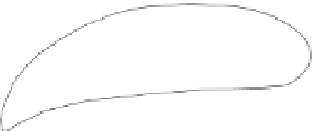
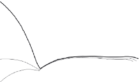
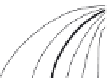
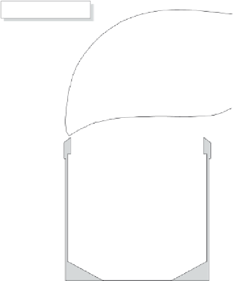
Fig. 3.20 Normalized velocity contour lines, derived from wind-tunnel measurements in and around a standard
British Mk2 precipitation gage, in its vertical plane of symmetry parallel to the flow. The reference air
velocity in the tunnel was3ms
−
1
from left to right; the dimensions are normalized with the outer
diameter of the gage, which is 136.6 mm. The wind velocities above the gage orifice can be seen to be
about 35% higher than the free-stream velocity. (From Nespor and Sevruk, 1999.)
speed increase above its orifice and the development of wake eddies around it. This, in
turn, tends to carry the finer precipitation particles over the orifice, thus decreasing their
number entering the gage. This effect increases with height of the orifice. Therefore, it can
be expected that the discrepancy between actual and measured precipitation will increase
with increasing wind speed, with decreasing precipitation intensity and with increasing
height of the gage orifice above ground level. Figure 3.20 illustrates the distortion of
the wind field above a rain gage, as derived from wind-tunnel measurements by Nespor
(1993; see also Nespor
et al
., 1994; Nespor and Sevruk, 1999); it can be seen how in
this case the velocity of the air above the gage is about 20% to 30% higher than in the
approaching undisturbed wind field. The losses in precipitation due to wind range on
average between 2% and 10% for rain, and between 20% and 50% for snow; however,
they may be much larger during individual precipitation events. Typical catch deficiencies
in relation to wind as the only factor are shown in Figure 3.21. A more detailed analysis