Geology Reference
In-Depth Information
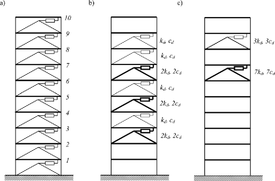
Figure 12. A 10-storey frame with different distributions of dampers: a) structure with uniformly dis-
tributed dampers, b) structure with optimally located dampers modelled using fractional Kelvin model,
c) structure with optimally located dampers modelled using fractional Maxwell model
In this example the objective function is the
weighted sum of amplitudes of the transfer func-
tions of interstorey drifts calculated at the funda-
mental natural frequency of the structure with
dampers. All weight factors are equal to 1.0, i.e.,
w
=
[ . ,
value of the objective function is obtained. When
the first damper's location is determined, the
procedure is repeated until all locations for the
dampers are found. The optimal locations of ten
successive dampers are found to be: no dampers
on the first, second and tenth storeys, one damp-
er on the fourth, sixth, eighth, and ninth storeys,
and two dampers on the third, fifth, and seventh
storeys for the fractional Kelvin model (see also
Figure 12b). In the case of the fractional Maxwell
model, the optimal locations of dampers are:
seven dampers on the seventh storey and three
dampers on the ninth storey (see also Figure 12c).
The dynamic properties of structures with opti-
mally distributed dampers are shown in Tables 5
and 6. It can be noticed that the non-dimensional
damping ratio of the first mode of vibration is
T
.
A first solution to the optimization problem
is obtained using the sequential optimization
method. For every possible location of one damper,
the values of fundamental frequency and non-
dimensional damping ratios are calculated (see
Figure 13 and 14). Next, the objective function is
evaluated for the frame, taking into account every
possible position of the damper. The results are
presented in Figure 15.
The correct fixed location of the first damper
is at the seventh storey, for which the minimum
1 0 1 0
. , ...,
1 0
. ]
Search WWH ::

Custom Search