Geology Reference
In-Depth Information
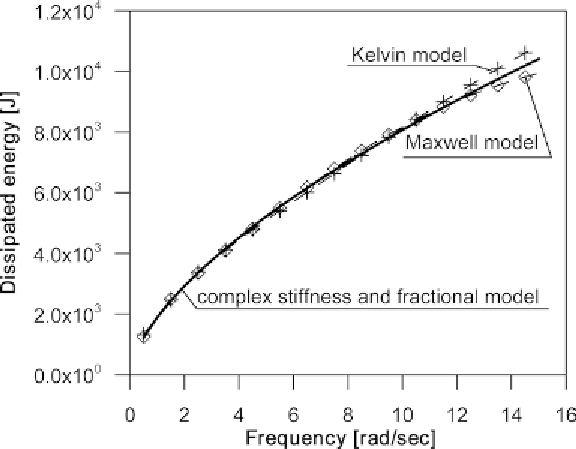
Figure 7. Comparison of dissipated energy
sidered structure. Chevron braces are used to
connect the dampers with the structure. The
braces are made of wide flange beams HEB 200
stainless steel profiles of which the parameters
a r e :
that the eight dampers must be optimally located
within the structure. Moreover,
c
min
=
0 0
. The
sequential optimization method is used to deter-
mine the optimal position of the dampers. As a
result of the optimization procedure, an almost
uniform distribution of the dampers is obtained,
i.e., there are no dampers on the first and eighth
storeys, there are two dampers each on the third
and fifth storeys and only one damper is located
on each of the other storeys. The sequence of
successive optimal position of dampers was ob-
tained as follows: the first damper on the fifth
storey, the second damper on the third storey, the
third damper on the sixth storey, the fourth
damper on the third storey, the fifth damper on
the fourth storey, the seventh damper on the sev-
enth storey, the sixth damper on the second storey
and the eighth damper on the fifth storey. The
effect of introduction of VE dampers is shown in
Figure 8, where the top floor displacement of
frame versus a number of dampers is presented.
A significant reduction of displacement is visible.
Introduction of the first few dampers is the most
effective. At the end of the optimization process
.
1 60105 10
9
EA
=
.
×
N
a n d
. Nm
2
, where
E, A
, and
J
is
the Young's modulus, the area of the cross section,
and the moment of inertia of the cross section,
respectively.
Here, the objective function is the maximum
value of the modulus of the transfer function of
horizontal displacement for the top floor, evalu-
ated at the fundamental natural frequency of the
frame with dampers. This function is the appropri-
ate element of vector
H
1 1685 10
7
EJ
=
×
= −
defined
above. The values of weight coefficients are equal
to zero except for one of them, which is equal to
1. The modulus of transfer function of different
kinds was widely used in the objective function
considered by Takewaki (2009). It is assumed that
the value of the main damping factor is
c
d
,
λ
H Mr
λ
( )
( )
3
8 67
=
MNs/m
and that the total capacity
of the dampers is
C
d
=
69 . MNs/m
. This means
.
Search WWH ::

Custom Search