Geology Reference
In-Depth Information
0
0
ones
the proposed GMGA and benchmark controllers
while the uncontrolled responses are used as a
baseline. As seen in Figure 13, the performance
of the proposed GMGA is slightly better than the
one of the benchmark control system. Figure 14
compares the dynamic responses of the 3D build-
ing structure. It is demonstrated that the newly
proposed algorithm is very effective in reducing
the dynamic responses of seismically excited
large-scale building structures. Note that it can
be found that the performance of the GMGA is
nearly the same with NS2-, and SP2-IRR GAs
from Figure 11 and Figure 12, however the CPU
running time is highly reduced by using GMGA
as shown in Figure 15.
ndof
×
1
F
m
=
.
(28)
ndof
×
1
−
ndof
×
1
where
ndof
is 20 for the 20-story 2D model and
60 for the 20 story 3D structural model,
G
is a
vector defining the loading of ground acceleration
onto the evaluation model, and
f
a
is the control
device force of 1000 kN.
Simulation
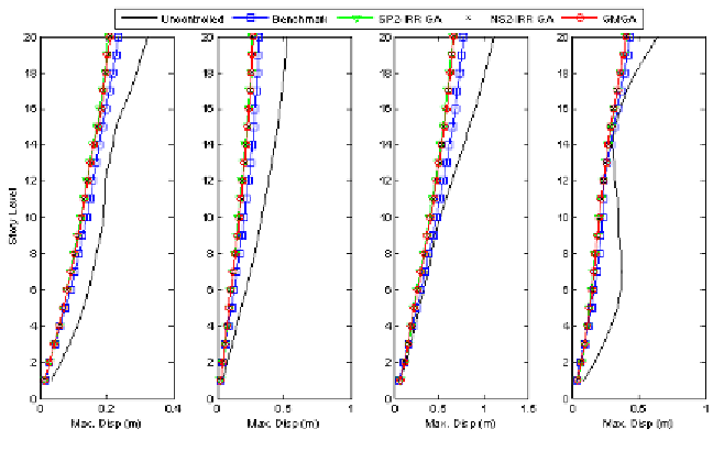
Figures 11 and 12 for the 2D twenty-story building
compare the maximum displacements and drift re-
sponses respectively, under a variety of earthquake
excitations: El-Centro, Hachinohe, Northridge,
Kobe earthquakes. As shown in the figures, all
the proposed algorithms (IRR-NS2 GA, IRR-SP2
GA, and GMGA) improve the performance of
the benchmark control system. Figure 13 shows
the time histories of displacement responses of
FUTURE RESEARCH DIRECTIONS
The near-optimal locations and numbers of the
sensors are critical to the active control perfor-
mance to reduce structural responses and damage
Figure 11. Maximum displacement responses (El-Centro, Hachinohe, Northridge, and Kobe earthquakes)
Search WWH ::

Custom Search