Geology Reference
In-Depth Information
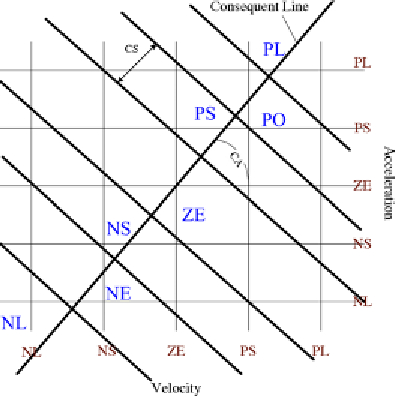
Figure 1. Fuzzy optimal rule base design strategy
Adaptive Rule Base Design
A geometric approach has been adopted to opti-
mize the rule base, such that it takes fewer variables
for rule base optimization. In this approach we keep
the symmetry in the rule base as shown in Table
2 about the premise [0; 0] intact. The following
assumptions consistent with structural control
design are made while designing the rule base.
•
To design an optimal rule base for the
structural system we take advantage of the
fact that control force input to the struc-
ture should increase when the structural
responses increases, i.e., the extreme input
values (premise) result in an extreme out-
put values (consequent), mid-range input
values result in mid-range output values
and small/zero input values result in small/
zero output. This rule base pattern is true
for both the negative and positive portion
of universe of discourse (UOD).
an optimal rule base we define a consequent line
as shown in Figure 1. The line is made pivotal on
premise zero-zero position (i.e., both inputs being
zero) and it is free to rotate over the consequent
space and therefore the rule base adapts according
to the optimization scheme. Each region represents
a consequent fuzzy set. It is to be noted that the
rule base remains symmetrical whatever be the
position of the consequent line.
The rule base is extracted by determining the
consequent region in which each premise combi-
nation point lies. The geometric approach is made
possible using only two parameters (CA and CS).
•
Larger control force is provided by the MR
damper with larger input current. Therefore
input current to the MR damper is consis-
tent with the structural responses.
To describe the optimization approach we
define a 'premise coordinate system' which is as
shown in Figure 1, a coordinate system formed
by the MFs of the two inputs relative velocity and
acceleration. The consequent MFs are to be placed
at the nodal locations formed by the connection
of two MFs of each input variables.
1.
Slope of the Consequent Line Angle (CA):
It has been used to create different output
space partitions. The angle is encoded to
cover angles between 0 − 180
◦
. As the conse-
quent space is symmetric and the output u(t)
ranges between [0, 1], 0−180
◦
is equivalent
to 0 − 360
◦
.
2.
Consequent-Region Spacing (CS):
As
shown in Figure 1, CS represents the space
spanned by each of the consequent variables
i.e., (NL, NE, NS, ZE, PS, PO, PL) over the
consequent region. A CS of value one is used
Encoding the Rule Base for
Optimization
In this geometric approach the consequent space
is overlaid upon the 'premise coordinate system'
and is in effect partitioned into seven small non-
overlapping regions, where each region represents
a consequent fuzzy set (see Figure 1). To design
Search WWH ::

Custom Search