Geology Reference
In-Depth Information
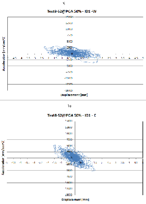
Figure 25. Hysteresis cycle of dissipating devices at the first floor: a) West panel; b) East panel
panel was inefficacious in the subsequent tests,
as showed by the hysteresis cycles reported in
Figure 25a.
maximum seismic energy entering the structure.
This procedure has been used to determine the
geometry of four different panels, differing for
the maximum transversal load that they can act
when inserted in a structure.
The optimized configurations of the panel have
been then modeled using ANSYS FEM software in
order to calculate the non-linear structural behavior
and the maximum transversal top displacement
tolerable before the beginning of elastic instabil-
ity phenomena.
A simple design method of choosing the most
appropriate panel to be inserted into a structure to
protect it from a seismic point of view has been
proposed.
CONCLUSION
The purpose of this research was to design a new
energy dissipation device to be used for passive
seismic protection of structures. The dissipater
is made of steel and aluminum and its geometric
configuration was determined using a structural
optimization routine. The optimization method is
simple and has been arranged to adapt its behavior
to the demands of the device in dissipating the
Search WWH ::

Custom Search