Geology Reference
In-Depth Information
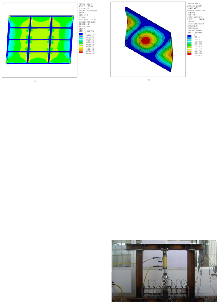
Figure 13. a) Plastic deformation and b) instability mode of the 100 kN device with 12 openings
CHARACTERIZATION TESTS
and one acting downward at the junction between
the two devices for a maximum load of 40 kN.
The test frame was used to perform tests on
the following devices:
Testing Setup
The test equipment was designed to reproduce
the working conditions of the panels in the 3D
frame previously described. In particular, a steel
frame consisting of a base beam (HEB 120), two
vertical elements (HEB120) and a top beam (HEB
120) was built (Diaferio et al. WCEE 2008, Di-
aferio et al. 2009). At the center of the top beam,
a 250-kN actuator Enerpac was connected. In
this way, it is possible to apply a load cycle to
a pair of panels, installed in the frame as shown
in Figure 14. Consequently, the load transmitted
from the actuator is divided equally into the two
panels, even in the presence of distortions or
misalignments. The panels are perfectly fixed in
correspondence of the columns, which are bolted
in the same manner provided for mounting the
3D frame for the shaking table tests (see par. 4),
while at the top, considering the symmetry of
the test system, the panels can only be subjected
to vertical displacements. By using the software
SAP2000, the test frame has been verified in cor-
respondence of the maximum applied load of 80
kN, assuming the frame to be externally isostatic
and loaded by two forces of 80 kN, one acting
upward in the middle of the top transverse beam
•
Device of 20 kN
•
Device of 20 kN, without the central alu-
minum plate
•
Device to 40 kN
•
Device to 40 kN, without the central alu-
minum plate
Tests have been carried out at the Laboratory
“M. Salvati” of the Department of Civil and
Environmental Engineering of the Technical
University of Bari.
Figure 14. Testing frame
Search WWH ::

Custom Search