Geology Reference
In-Depth Information
Figure 5. Geometrical parameters of the aluminum-steel device
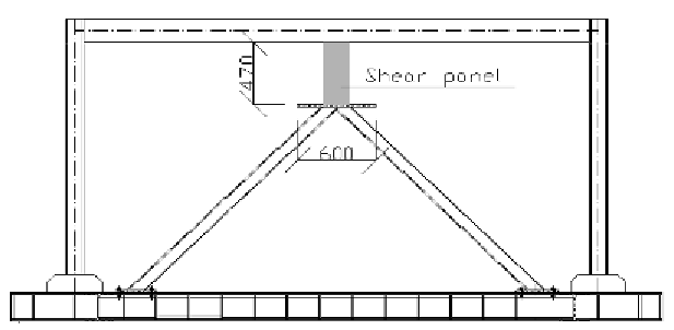
Figure 6. Positioning of the device in the structure
with commercial FEM code, simple to use and
with a relatively low computing time. In particular
optimization method consists in a random design
generation followed by a sub-problem approxi-
mation run that were performed using ANSYS
program. A solid FEM model of the panel has been
built for the optimization analysis using element
SOLID90 at 20 nodes, having a parabolic shape
function. Maximum dimension of elements in
thickness direction was fixed to 0.5 mm, therefore
the number of nodes were about 15000, depending
from the design values of the plate thickness. The
mechanical behavior of steel and aluminum has
been described by a bi-linear behavior, whose pa-
rameters were defined according to the properties
listed in Table 1. In this analysis, the panel was
modeled as fixed at the base and with a double
pendulum at the top, to reflect the installation of
the device in a frame (Figure 6).
The load condition considered for the optimiza-
tion analysis corresponds to a top displacement of
the panel of 4 mm, equal to 0.2% of the interstory
height of the frame, the last being between 2.5 and
3.0 m. This top displacement must be maintained
due to the working constraint of the shaking-table
used for the experimental test.

Search WWH ::

Custom Search