Geology Reference
In-Depth Information
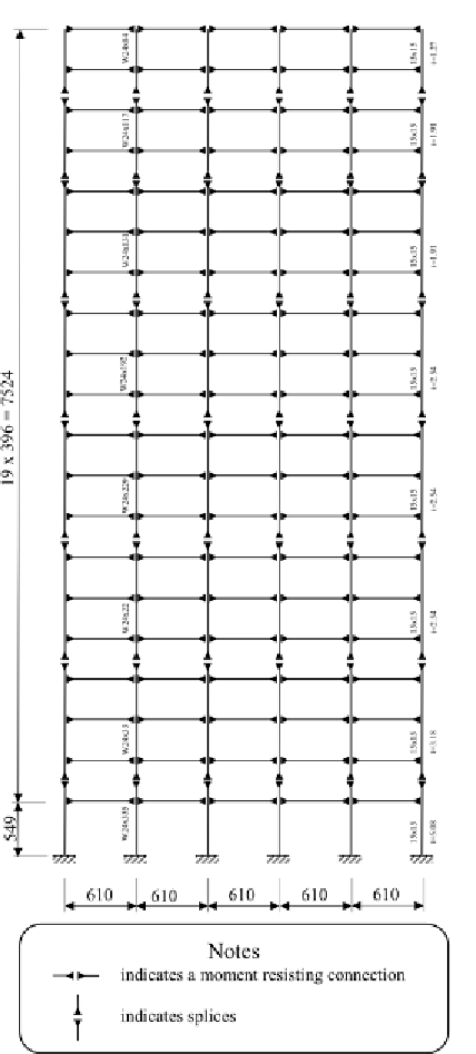
Figure 3. Twenty story steel frame structure
Following Ribakov (2003), the lever arm de-
flection
Δ
should be limited by a permitted value,
Δ
perm
, say a proportion of the whole drift
d
:
∆ ∆
≤
= ⋅
k d
(16)
perm
where
k
is a factor smaller than 1
The effective amplifying ratio of the lever
arm system, considering the losses due to bend-
ing,
AR
is
AL d
d
⋅ −∆
AR
=
(17)
As it was mentioned above, the losses due to
lever arm bending do not require any increase of
the optimal control force. They yield additional
control energy because the real displacement of
the actuator is
d
d AL
act
= ⋅
+∆
(18)
Knowing the required peak control forces,
obtained according to the LQG algorithm, and
the maximum forces that may be developed by
commercially available actuators, geometry of
lever arm amplifiers can be obtained. The section
of each lever arm can be selected using the basic
design provisions for steel bending elements.
NUMERICAL EXAMPLE
To demonstrate the effectiveness of the proposed
method structural seismic response was simulated
using originally developed MATLAB routines.
The structure selected for this study is a twenty
story steel frame shown in Figure 3. It is similar
to that used by Spencer
et al.
(1999). The natural
damping ratio was assumed to be 2%.
Optimal distribution of dampers for different
number of “active” floors was obtained using the
above described procedure. An artificial white
noise ground motion with PGA = 0.3g, BW = 30
Hz,
t
f
= 50 s. was used for this reason. The
maximum control force at each damper during
this stage was limited to 10% of the story weight
and the maximum control force at each floor was
Search WWH ::

Custom Search