Geology Reference
In-Depth Information
damper force and yields the desired damping ef-
fect. Using “scissor-jacks” results in a relatively
lower number of damping units required to obtain
optimal distribution of devices, compared to
toggle braces.
Lever arms (Figure 1c) are proposed to increase
the efficiency of damping devices by magnifying
the inter-story drifts and drift velocities, transferred
from the structure to dampers (Gluck, 1996). This
idea was further developed for design of structures
with optimal viscous dampers (Ribakov, 2000).
The “equivalent” lever arm approach is used to
change the effect of off the shelf linear viscous
devices yielding an optimal passive control system.
Other effective mechanical amplifying systems
are also used for connecting semi-active and ac-
tive dampers in order to reduce the control forces
and the energy required for activation of control
devices (Gluck, 2000, Ribakov, 2000). In this
study efficiency of lever arm amplifiers for con-
nection of active controlled devices is studied. First
optimal locations of control devices are obtained.
The amplifiers are used for further decreasing the
number of control devices at each floor.
The efficiency of amplifiers can be substan-
tially reduced due to the deformations of con-
necting elements. A design procedure for lever
arm amplifiers, compensating for the bending of
structural levers was proposed by Ribakov (2003).
It was demonstrated that the proposed design tech-
nique is efficient in viscous damped structures. It
was shown that the effectiveness of the lever arm
amplifier increases for larger amplifying ratios,
which depends on the geometry of the system and
on the stiffness of the lever arm itself.
If a viscous device is connected to a lever arm,
the lever arm deflection decreases the amplifica-
tion effect. For active controlled actuators the
control force usually does not depend on velocity,
but the lever arm deflection increases the energy,
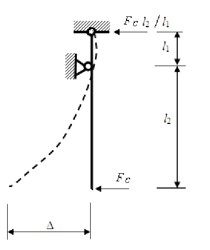
required for activation of actuators. Following
Ribakov (2003), when the desired amplification
is determined from other considerations, the
height of the Chevron brace
l
2
(Figure 2) can be
obtained as:
H AL
AL
l
=
st
(13)
2
+
1
where
H
st
is the story height and
AL
is the ampli-
fying lever ratio for the case of a rigid lever arm:
AL
=
2
l
/
l
(14)
The deflection of the lever arm at each time
increment can be expressed as:
2
2
F l
EI
F l
EI
(
)
=
c
2
c
2
∆=
l
+
l
H
(15)
1
2
st
3
3
LA
LA
where
F
c
and
I
LA
are the force in the actuator and
the inertia moment of the lever arm, respectively.
Figure 2. Lever arm calculation scheme

Search WWH ::

Custom Search