Geology Reference
In-Depth Information
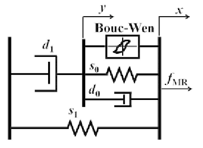
Figure 7. Schematic of the mathematical model
for the MR damper
where
z
and
y
are the states and output vectors;
A
,
B
,
C
,
D
,
E
are the state, the input, the output,
the feedforward, the disturbance location matrices,
respectively;
n
is the noise vector, and
z
1
and
z
4
are the displacement and the velocity at the 1
st
floor level of the three-story building structure,
respectively. Note that in the earthquake engineer-
ing applications, the earthquake disturbance ex-
cites all the floor levels within the building
structure as the inertia forces, i.e.,
w
g
is a vector
with a dimension of 3 × 1 instead of a scalar
value. Using this building-MR damper system,
the performance of the proposed hybrid clipped
BEL-PID control algorithm is investigated.
MR Damper
1
{
}
y
=
α
BW
z
+
d x
+
s x
(
−
y
) ,
0
0
(
d
+
d
)
In recent years, smart control systems have been
proposed for large civil structures because the
smart control strategies combine the best features
of both active and passive control systems. In
particular, one of the controllable-fluid dampers,
MR damper as shown in Kim et al. (2009) has
attracted considerable attention in recent years
due to its appealing characteristics: reliable op-
eration; fast response time; low power require-
ments; broad temperature range; adjustable op-
erating points; and low manufacturing cost. To
make the fullest use of the advantages of the MR
damper, Spencer et al. (1997) proposed a modified
version of the Bouc-Wen model, as shown in
Figure 7. The MR damper force
f
0
1
(16)
α
=
α
+
α
b
u
,
(17)
a
d
1
=
d
+
d u
,
(18)
1a
1b
d
0
=
d
+
d u
,
(19)
0a
0b
u
= −
η
(
u
−
v
),
(20)
where
z
BW
and
α
,
called evolutionary variables,
describe the hysteretic behavior of the MR
damper;
d
0
is the viscous damping parameter at
high velocities;
d
1
is the viscous damping param-
eter for the force roll-off at low velocities;
α
a
,
α
b
,
d
0a
,
d
0b
,
d
1a
, and
d
1b
are parameters that account
for the dependence of the MR damper force on
the voltage applied to the current driver;
s
0
controls
the stiffness at large velocities;
s
1
represents the
accumulator stiffness;
x
0
is the initial displacement
of the spring stiffness
s
1
;
γ, β, n
and
A
are adjust-
able shape parameters of the hysteresis loops, i.e.,
the linearity in the unloading and the transition
MR
( )
predicted
by the modified Bouc-Wen model is governed by
the following differential equations:
t
(
f
MR
=
d y
+
s x
−
x
),
(14)
1
1
0
z
=
BW
n
−
1
n
−
γ
x
−
y z
z
−
β
(
x
−
y z
)
+
A x
(
−
y
),
BW BW
BW
(15)

Search WWH ::

Custom Search