Geology Reference
In-Depth Information
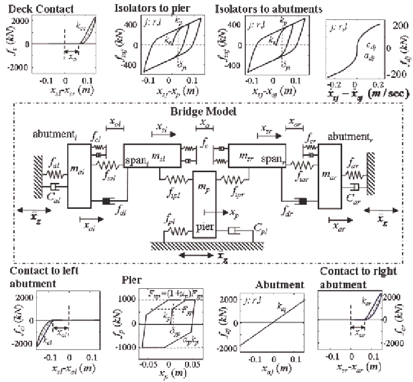
Figure 3. Schematic model for two-span bridge system with seismic isolators and supplemental dampers
where
x
g
is the ground acceleration;
f
c
,
f
cl
and
f
cr
are the impact forces due to pounding between
the two spans or between the spans and the left
or right, respectively, abutments;
f
dl
and
f
dr
are the
left and right damper forces; and
f
ial
,
f
ipl
or
f
iar
,
f
ipr
are the forces of the isolators that support the left
or right span of the bridge to the abutment and
the pier, respectively;
f
p
corresponds to the restor-
ing force for the pier which is modeled as hyster-
etic bilinear force with ultimate strength as de-
picted in Figure 3. Strength and stiffness
deterioration may be additionally incorporated
hicle traffic. Additionally let
C
p
,
C
al
,
C
ar
denote,
respectively, the damping coefficient for the pier
and the left and right abutment. The equation for
the seismically isolated system is then derived by
equilibrium conditions as:
(
)
+
m x
+
f
+ +
f
f
f
+ =
f
0
sl
sl
ial
cl
dl
ipl
c
(
)
+
m x
+
f
+ +
f
f
f
− =
f
0
sr
sr
iar
cr
dr
ipr
c
m x
+
C x
+ −
f
f
−
f
= −
m x
p
p
p
p
p
ipl
ipr
p g
(
)
= −
+ −
m x
+
C x
f
f
+ +
f
f
m x
al
al
al
al
al
ial
cl
dl
al
g
(
)
= −
m x
+
C x
+ −
f
f
+
f
+
f
m x
ar
ar
ar
ar
ar
iar
cr
dr
ar
g
(4)
Search WWH ::

Custom Search