Geology Reference
In-Depth Information
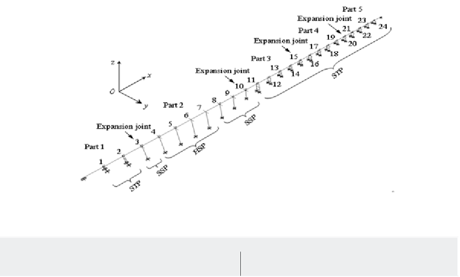
Figure 2. Finite element model of the continuous girder bridge
Table 1. Seismic demands of the original continuous girder bridge
Soil type I condition
Soil type III condition
Bending
stiffness(×10
3
kN/m)
Disp.
(m)
Shear stress
(MPa)
Normal stress
(MPa)
Disp.
(m)
Shear stress
(MPa)
Normal stress
(MPa)
Pier No. Pier type
1
STP
521.0
0.024
4.630
4.340
0.047
9.290
8.710
2
STP
52.60
0.047
0.960
1.170
0.095
1.890
2.320
3
SSP
7.640
0.071
0.390
7.630
0.140
1.460
15.800
4
HSP
3.170
0.066
0.071
4.740
0.130
0.220
8.960
5
HSP
2.800
0.061
0.079
4.380
0.120
0.220
7.760
6
HSP
2.490
0.055
0.110
4.890
0.110
0.280
7.470
7
HSP
2.800
0.050
0.082
3.840
0.100
0.200
6.180
8
SSP
6.320
0.047
0.260
4.160
0.095
0.660
7.410
9
SSP
11.70
0.043
0.260
4.820
0.086
0.880
9.850
10
SSP
29.20
0.039
0.650
9.160
0.078
2.590
18.290
this consideration, a new-type pier, named as close
twin-column pier (CTP), is proposed to upgrade
some piers of the bridge (Figure 3). The CTP is
built by vertically dividing the SSP into two parts
along the axial symmetrical plane but close to
each other. The pier's transverse stiffness can be
reduced by 45% to 50%, but the longitudinal
flexural stiffness is still maintained. Hence the
corresponding acceleration amplification is re-
duced greatly in the transverse direction. Accord-
ingly the piers No. 3, 8, 9 and 10 are selected to
be replaced by the CTP and the response spectrum
analysis results are shown in Table 2.
Comparing the results in Table 2 with Table
1, it can be seen that all the stress demands and
some displacement demands are greatly miti-
gated after some of the bridge piers are changed
to the CTPs. Although the pier top displacement
demands at pier No. 5 to pier No. 10 increase in
some degree, the values themselves are still small
and do not exceed the requirements of the code
(Ministry of transport of the People's Republic


Search WWH ::

Custom Search