Geology Reference
In-Depth Information
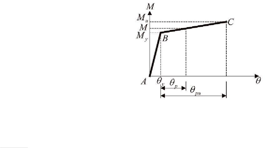
Figure 2. Moment-rotation curve
Eq.(4). During the inelastic drift design optimiza-
tion process,
u
j mem
,
is kept unchanged since
B
i
and
D
i
of each member section are fixed. The
emphasis here is on the displacement,
u
j hing
,
,
caused by the formation of the plastic hinges. In
Eq. (15),
m
pj
0
is the virtual end moment at the
location of the hth hinge of a member;
θ
ph
is the
actual plastic rotation experienced by the hth
plastic hinge, which is equal to zero when no
plastic hinge is found. As shown in Figure 2, the
behaviour of a plastic hinge is modelled as a bi-
linear curve: the elastic segment, AB, and the
hardening segment, BC. Based on the line seg-
ments A-B-C, the plastic rotation,
θ
p
, can be
given as follows
the inelastic optimization process requires a cor-
responding update on the values of
M
and
M
y
.
In pushover analysis, pure moment hinges as
well as axial moment hinges are widely used and
are generally assigned to the two ends of each
beam or column. In fact, the inelastic displace-
ment,
u
j hing
,
, in Eq. (13) includes the displacement
generated by moment hinges (usually in the beams)
and that generated by axial moment hinges (usu-
ally in the columns). By the force equilibrium
shown in Figure 3, where
f
c
is the stress at the
extreme compression concrete fibre,
′
M M
M M
−
−
y
θ
=
θ
U
≤
θ
U
(16)
p
p
p
u
y
where
θ
U
is the ultimate plastic rotation which
can be established based on experimental tests or
can be obtained directly from design guidelines
such as the ATC-40 (1996);
M
is the applied
moment at the location of the plastic hinge;
M
y
is the bending moment at the first yielding of the
tensile steel; and
M
u
is the ultimate moment of
resistance. Given the quantity of the steel rein-
forcement used in a concrete section, the values
of
M
y
and
M
u
can then be determined. For sim-
plicity,
M
u
can be approximately related to
M
y
as
M
u
=
1 .
M
y
(ATC-40 1996). For the explicit
problem formulation, it is necessary that the
plastic rotation,
θ
p
, be accurately expressed in
terms of the design variables (i.e.,
ρ
and
ρ
'
).
Furthermore, a good formulation should reflect
accurately the change in the plastic rotation,
θ
p
,
due to a change in the design variables during the
optimization resizing process. In other words, any
change in the design variables,
ρ
and
ρ
, during
f
s
is the
stress in the compression steel,
f
y
is the yield
strength of the tension steel, and d is the effective
depth, which is equal to the distance from the
extreme compression fibre to the centroid of the
tension steel,
M
y
for a moment hinge (where there
is no co-existent axial force) can be expressed in
terms of design variables,
ρ
and
ρ
, as
f Bkd
kd
M
=
0 5
.
(
−
d
')
+
f Bd d
(
−
d
')
ρ
y
c
y
3
(17)
where
k
is the neutral axis depth factor at the first
yield and it is given as
Search WWH ::

Custom Search