Geology Reference
In-Depth Information
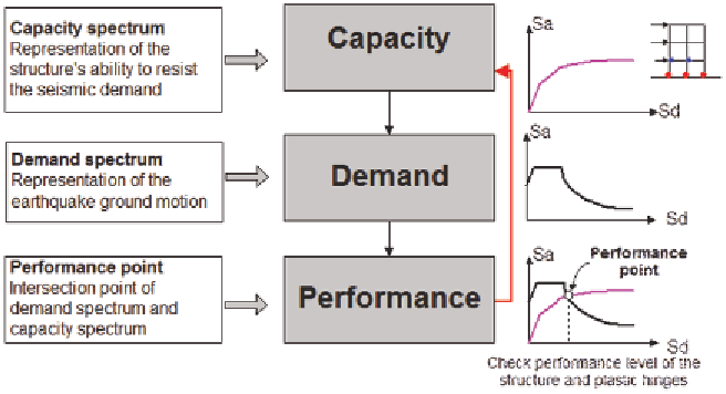
responses can be checked against acceptability
limits on both global system levels (such as the
lateral load stability and the inter-story drift) and
local element levels (such as the element strength
and the sectional plastic rotation) (ATC-40 1996).
When the responses of a structure do not meet the
targeted performance level, the structure needs to
be resized and the design process repeated until
a solution for the desired performance level is
reached. In general, the determination of the satis-
factory performance response that fulfils both the
system level response and element level response
requires a highly iterative trial-and-error design
procedure even with the aid of today's finite ele-
ment analysis software.
element to be used to control the inelastic perfor-
mance of the structure. Based on these consider-
ations, in the second phase, the tension steel re-
inforcement ratio,
ρ
i
, and the compression steel
reinforcement ratio,
′
ρ
i
, of rectangular cross sec-
tions are taken as design variables, for a flexural
concrete building having
i
=1, 2,?,
N
i
members
and 2
N
i
plastic hinges (assuming one hinge at
each end of a member). The width
B
i
and depth
D
i
of the cross section are fixed in this phase.
If the topology of a building structural system
is predefined, the design objective of the reinforced
concrete framework in the second inelastic design
phase is to minimize the steel reinforcement cost
f
1
, which can be expressed in terms of steel re-
inforcement design variables:
2.2.2 Design Optimization Problem and
Explicit Drift Formulation
Minimize: steel cost
N
i
∑
(
+
′
′
f
=
w L
ρ
L
ρ
)
(10)
While the concrete material plays an important
role in controlling the elastic displacement re-
sponse of a RC building, the steel reinforcement
can have a significant effect on the inelastic dis-
placement and ductility of the RC building beyond
the linear elastic limit. Moreover, when an RC
structure works in the inelastic stage, steel rein-
forcement is generally the more cost-effective
1
s
si
si
i
si
i
i
=
1
where
w
si
is the cost coefficient for steel reinforce-
ments; and
L
si
and
′
L
si
are the lengths of the
lower and upper steel reinforcements for member
i
. Herein, only the longitudinal reinforcement of
member sections is considered as design variables
and the transverse reinforcement is assumed to
Figure 1. Nonlinear analysis procedure
Search WWH ::

Custom Search