Geology Reference
In-Depth Information
Box 2.
N
i
( )
=
∑
1
Minimize
F
ρ
W
ρ
i
si
i
i
=
(50)
N
N
1
1
2
i
i
2
(
)
+
(
)
( )
=
∑
∑
≤
Subject to
:
g
ρ
δ
∆
(
ρ
0
)
+
Ψ
×
ρ
−
ρ
0
Ψ
× −
ρ
ρ
0
d
U
j
=
1 2 3
,
,
, ....
N
j
i
j
1
i
i
i
2
i
i
i
j
j
h
j
i
=
1
i
=
1
ρ
L
≤ ≤
ρ
ρ
U
i
=
1 2 3
,
,
, ....
N
i
i
i
i
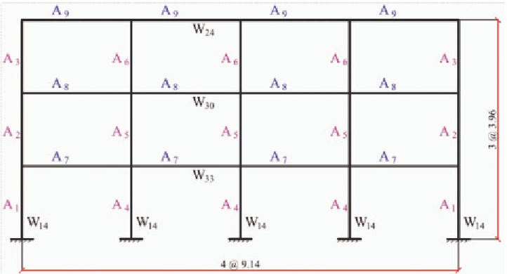
To optimize the design of this frame under
applied earthquake load, Xu et al. (2006) consid-
ered a combination of two objective functions for
this example. The first is F
1,
a measure of weight
of the structure, and the second is F
2
, a measure
of uniformity of distribution of relative drift (see
Box 3).
In Eq.(51), Δ and H stand for lateral displace-
ment and height, respectively; r and s represent
the roof and story;
A
i
U
is the upper bound of area
A
i
of member i. ω
1
and ω
2
are named combination
factors, and for this example they were taken
ω
1
=0.95 and ω
2
=0.05. The first objective function,
F
1
, is an explicit function of design variables,
A
,
while the second objective function, F
2
, is an
implicit function of design variables. Xu et al.
used one set of constraints, C
1
, in Eq.(41). The
constraints of group C
3
as well as C
5
, were
treated as side constraints; i.e. they were checked
after analysis; if they were violated, the design
was scaled via a proper way.
The pushover analysis of Hasan (2002) was
used for determining the displacements under ap-
plied earthquake load at IO, LS and CP levels. To
express the objective function explicitly in terms
of design variables, as a requirement of Eq.(16),
the derivative of F
2
had to be calculated using a
proper sensitivity analysis technique. Xu et al.
(2006) realized that a better approximation can be
obtained using reciprocal variables. Accordingly,
they reformulated the problem it terms of recip-
rocal variables and used the sensitivity analysis
technique of Gong (2003), i.e. Eq.(30) for the
Figure 9. A three story four bay moment frame, (Xu et al. 2006)


Search WWH ::

Custom Search