Graphics Reference
In-Depth Information
F
A
A
B
(a)
(b)
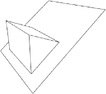
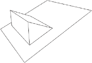
Figure 12.24
Two alternatives to resolving a single concave edge
A
. (a) Cutting to the plane
through
A
and some other edge
B
. (b) Cutting to the supporting plane of one of its neighboring
faces
F
.
A
B
F
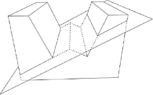
Figure 12.25
Cutting (here to the supporting plane
of face
F
, neighboring the selected
concave edge) with the intent of cutting off part
A
can have the unintended global effect of
also cutting off part
B
.
π
The polygons straddling the cutting plane form two disjoint “contours”: one local
to the
A
part, one local to the
B
part. By limiting the cutting to occur at the contour
having connectivity to the original concave edge, the correct behavior is obtained
(which here is cutting off part
A
only). After the cut, the geometry both in front and
behind the planes will have open holes (in the shape of the contours) that must be
filled in. These holes are closed by creating a polygon in the shape of the contour and
connecting it to the rest of the geometry.