Graphics Reference
In-Depth Information
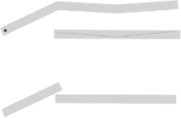
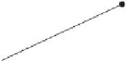
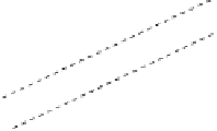
Figure 12.15
The upper illustration shows how an absolute merging tolerance smaller than
the plane thickness tolerance (in gray) avoids cracks from appearing between neighboring
faces. The lower illustration shows how a crack may appear when the merging tolerance
exceeds the plane thickness tolerance.
Worse, if vertices are unwelded and are allowed to move during merging cracks can
appear at the edges between neighboring faces unless the absolute merging tolerance
is kept smaller than the plane thickness tolerance. Figure 12.15 illustrates how a crack
may appear between a face and a merged face when the merging tolerance exceeds
the plane thickness tolerance. To avoid tolerance issues that would cause robustness
problems and to guarantee the reduction of faces due to merging, it is important
to use an absolute error measurement for merging geometry for use with collision
detection.
12.4.2
Testing Polygon Planarity
A polygon is defined by a set of vertices in the plane. Testing the polygon for planarity
then involves making sure all defining vertices lie in a plane. This can be done by
computing a plane equation for the supporting plane of the polygon and then testing
all vertices to make sure they are within some tolerance of the plane. The plane
equation for the supporting plane is obtained through computing a polygon normal
and selecting a reference point on the polygon.
This sounds simple enough, but there is a hidden subtlety: how to compute the
polygon normal
n
(
n
x
,
n
y
,
n
z
). A first approach to computing the polygon nor-
mal might involve computing the cross product of two coincident polygon edges.
However, this is not robust because the edges may be (near) collinear, causing the
=