Graphics Reference
In-Depth Information
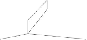
(a)
(b)
Figure 12.11
(a) A face meeting another face edge-on, forming a gap. (b) The gap resolved
by face cracking.
does not have to be performed when the vertices of the edge lie in the negative
halfspace of the supporting plane of the other face.
12.4
Merging Co-planar Faces
Edge and face cracking may introduce a fair number of extra faces to the collision.
Because collision detection speed decreases as the number of faces increases, it is
worthwhile incorporating an optimization step into the generation of robust collision
geometry to help reduce the number of faces.
Many methods have been suggested for model simplification. Thorough reviews
of the field are given in [Luebke02] and [Puppo97]. For collision detection, it is
very important to preserve both shape and volume to prevent the collision geometry
from “shrinking”inside the visual representation, allowing objects to interpenetrate
visually even though they may not actually be touching in a collision sense. Out
of the huge library of simplification methods, one approach particularly suitable for
collision detection geometry is that of merging (near) co-planar faces. Face merg-
ing also helps to remove sliver-like and other degenerate faces, which are usually a
source of robustness problems (see Chapter 11).
In addition to two faces being co-planar up to some given tolerance, some other
criteria generally must be fulfilled for two faces to be mergeable. Specifically, the faces
must:
both be either double or single sided, and face in the same general direction
when single sided,
●
have the same associated surface properties (footstep sounds, friction attributes,
or similar attributes), and
●
share one or more boundary edges.
●