Hardware Reference
In-Depth Information
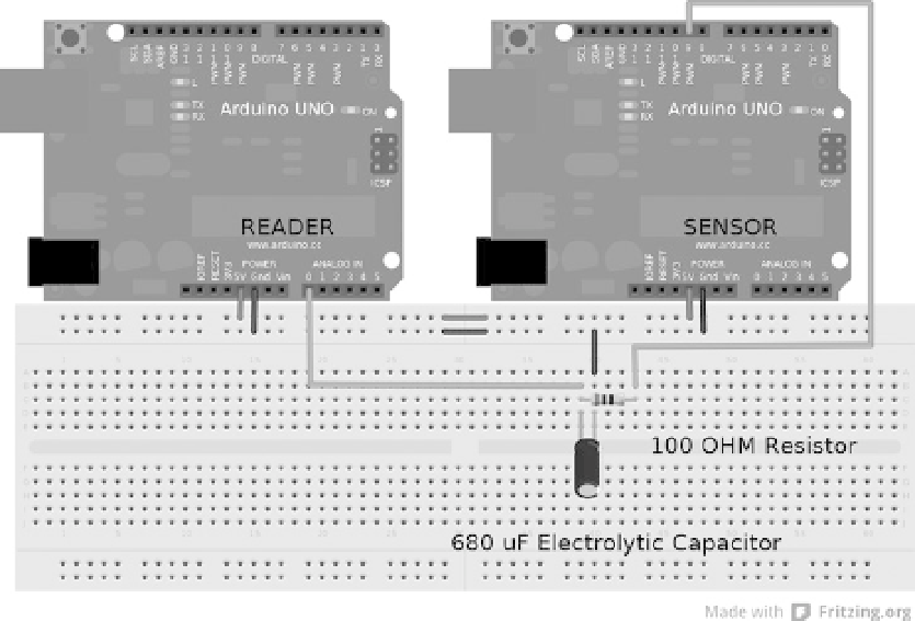
To set up the hardware, refer to Figure
6-1
; the 5V pins and one ground on each Arduino are hooked together so
the sensor Arduino can get power and to ensure that the Arduinos can communicate by having a common ground
(this is the same for all examples). The RC filter setup uses an electrolytic capacitor with the ground side hooked up to
Arduino ground and the positive side to analog in on the reader. On the sensor Arduino, pin 9 is connected to one side
of a resistor, and the other side is connected to the positive pin on the capacitor.
Figure 6-1.
RC low-pass filter setup
Listing 6-2 demonstrates the output by manipulating a variable that is declared as type
byte
and then written to
the PWM pin 9. Any type of manipulation can be performed on the
sensorOut
variable by receiving commands from
the serial monitor to set the output value, or computing a range to better match the sensor type being simulated (such
as one that sweeps from 0 to 100°C).
Listing 6-2.
Code to Be Uploaded to the Sensor Arduino
byte sensorOut = 0x00;
void setup() {
pinMode(9,OUTPUT); // serial can be set up here
}// end void setup()
void loop() {
sensorOut++; // the manipulation of the output variable
analogWrite (9,sensorOut); // the actual sensor simulation
delay(1000); // delay is to match the update speed of the sensor
}// end void loop()