Geology Reference
In-Depth Information
Galleries require a greater initial investment, but remain accessible
later on. They collect water through a system of drainage channels
opening at the base of the uphill wall.
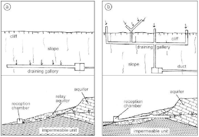
The collection basin is set into the impermeable terrain, parallel to the
slope, over a segment long enough to prevent lateral leakage (Figure 96a).
When water emerges from a relay reservoir, the catchment system can
also extend into the hillside in order to reach the initial reservoir, which
can increase productivity, but can also lead to very complex networks (a
few hundreds of meters of galleries). Drainage of the aquifer can fi nally be
complemented by rings of subhorizontal drains, drilled from a terminal
chamber in the gallery (Figure 96b).
Figure 96
Typical map and cross-section diagrams of drainage galleries, at the foot of a relay
aquifer (a) and extended to the original source (b).
Whatever the catchment system put in place (drainage gallery or
trench), the collected water is led to a reception area containing, as in the
previous case, a decanting basin and a header chamber, as well as a basal
drain, a fl ood drain, and a perforated segment of intake piping.
This method is also sometimes used in the upper part of the saturated
zone of an aquifer, either by herringbone-pattern trenches, or by a network
of galleries (for hillside and alluvial aquifers). Excavations are done in the
upstream direction, maintaining a high longitudinal slope in order to enable
graviationl fl ow. In the case of galleries, it is also possible to use extraction
Search WWH ::

Custom Search