Hardware Reference
In-Depth Information
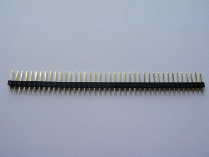
With this in mind you can buy pin headers. They come in many forms; you will need a single row of 16 pins.
In Figure
4-4
you can see the pin header I used.
Figure 4-4.
My pin header with 2-mm spacing
If your pin header is too long, just cut the extra pins off. The key thing to remember is that you need a single row
rather than a double row. The pin headers won't be much use unless you solder them on. Strangely enough they
won't do much sitting on your desk. If you take a look at your LCD you will see that the solder pads may only be on
one side of the PCB. On most of the LCDs I have seen, they are on the top. In my case they are on the top and bottom.
This is important so that you know what side to face the pin headers on. I will face my pin headers upward and make
use of the solder pads on the back of the LCD. In Figure
4-5
you can see the pin headers in place, before soldering has
started and in Figure
4-6
you can see the finished result. In the topic's introduction I mentioned jumper cables; this is
where they will come in handy. You can now connect any of the pins easily and without any possibility of damaging
the solder pads. It also looks a lot nicer. There is nothing worse than messy cabling or bad soldering jobs.