Hardware Reference
In-Depth Information
7.
Remember the pull-up resistor? I hope you do! It is an important part of the 1-wire bus.
You need to place this resistor in between the new row on your breadboard and your
3.3 V source. You then connect a hook-up wire from the opposite side of the row to P1-07
(GPIO-4) on your Raspberry Pi. Figure
3-13
will help you understand this.
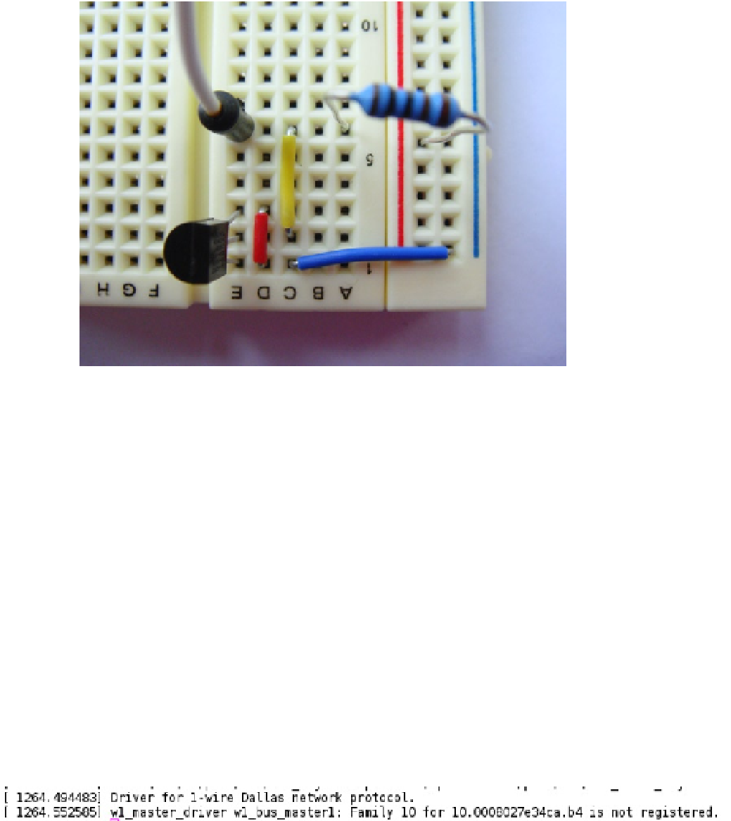
Figure 3-13.
Resistor and GPIO connected to the new row
All the connections are made now. Turn on your Raspberry Pi and turn on the power source for your breadboard.
You can connect the GPIO pins while the Raspberry Pi is powered on as well. You could also power the sensors from
the Raspberry Pi itself if you wanted to. I tend to avoid this as a safety measure.
Reading the DS1820B on Linux
There is a very good reason why I picked P1-07 (GPIO-4) on the Raspberry Pi. I did not just randomly select it. Recall I
spoke about the 1-wire protocol hijacking the serial port? You're going to do something similar with the GPIO. Lucky
for us now, in the stock Raspberry Pi kernel (after August 2012) the
w1_gpio
module has coded GPIO-4 as the 1-wire
bus. If this had not been done you would have needed to set this yourself in the source code for the
w1_gpio
module
and rebuild your kernel. Lucky for us, you don't need to. First, you're going to need to load the 1-wire bus support
because this module is not loaded by default. Run the following command to load the 1-wire bus:
# modprobe w1_gpio
When you do this, two things should happen if you've connected everything correctly. The first thing that will
happen is two messages will be printed in
dmesg
(see Figure
3-14
). You can see where the kernel loaded the 1-wire bus
and where the 1-wire master controller found a device.
Figure 3-14.
A 1-wire device is found