Hardware Reference
In-Depth Information
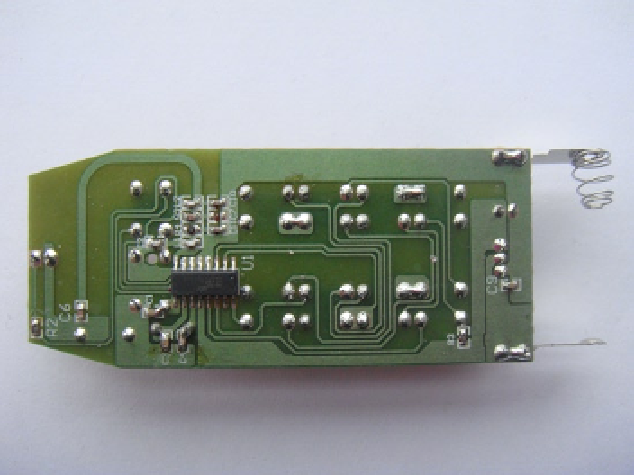
Figure 10-8.
The inside of the remote control unit
Most of the little tactile buttons you will find on remote controls will have four pins on the back side of the
remote: you don't need four pins to make a simple switch, because two are all that is needed. Four pin switches are
often used as they add stability to the mount of the switch. You may have noticed that all four pins are soldered into
the board. If you take an even closer look you will notice a few patterns between each set of switches. The first and
most obvious thing you may have noticed is that two pins between a switch set are simply joined together by a track
on the printed circuit board (PCB). This usually indicated the ground pin of the switch as it's easier to join the two
ground pins together than to route two separate tracks on the board itself. This will become one side of your circuit
on the breadboard. This now leaves three pins left.
You now need to find out what pin closes the circuit when the switch is pressed. There are two ways to do this:
•
The first way and the way I have used it is to set your multimeter to the ohms setting: connect
one probe to the ground pins you found before and then connect the other probe to any of
the remaining three pins. You will have two possible outcomes at this point. The multimeter
will either read a very high resistance (indicating no connection) or a very low resistance
(indicating a closed circuit, which means the switch connects the two pins). If you have found a
pin with low resistance then this will be the other side of your circuit on the breadboard. If this
pin was not the right one, move on to the next pin until you find a pin that has a closed circuit
when you press the switch in. It should not take long: there are only three choices after all.
•
The second way is to take a look at the PCB; in most of the cheaper remotes the PCB is a single
layer, which means you can visually trace each connection on the board. You want to trace the
pin that goes back to an integrated circuit (IC). Given that there should be only one IC, this is
a simple task. The other two pins will either be connected to nothing or connected to another
switch. What the other pins connect to is not important. You're only interested in the pin that
leads you back to the IC.
Now that you have worked that out, let's build the remote control part of the circuit:
1.
Take a look at Figure
10-9
to see how I have wired my remote. I have fully connected only
one switch to better display the pins of the switch. You will need to connect one ground
wire and one positive wire to each switch.