Hardware Reference
In-Depth Information
Now I have taken the approach to use two breadboards to build the sensor for testing purposes; obviously you
would need a length of wire attached to the PIR when you build this for real.
1.
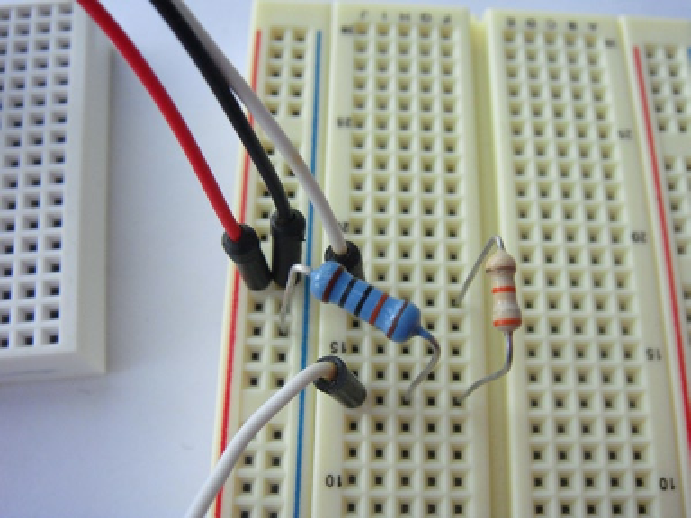
The resistor placement for this sensor is quite critical: if you get it wrong, your sensor just
won't work although you are unlikely to damage it: Install a 100K ohm resistor between
ground and one row of the breadboard. It's a good idea to place this on a slight angle as
you will need to access the holes on each side of the row.
2.
Next install the 39K ohm resistor on the inner side of the breadboard and place the other
leg of the resistor into a brand-new row.
3.
Connect the out pin of the PIR sensor to the same new row into which you placed the
other leg of the 39K ohm resistor.
4.
Now connect the Raspberry Pi's P1-11 GPIO to the power rail side of the 100K ohm resistor.
Take a look at Figure
5-13
for a close-up image of the resistor and GPIO pin connections.
Figure 5-13.
A close-up of the resistor placement
5.
Once that is done, connect your power rail to the Raspberry Pi's P1-01 3.3-V power and
connect the ground rail to the Raspberry Pi's P1-25 ground connector.
6.
Then place the PIR sensor on a small breadboard and extend the GPIO wire and the two
power rails to the PIR. Make sure you get the pins correct on the PIR. Check your data
sheet for how you should connect your sensor. In the case of the Panasonic AMN31111 you
can see the pin outs in Figure
5-14
.