Information Technology Reference
In-Depth Information
Refer to Figure 1-8. R1 received a packet from PC1 destined for PC2. R1 forwarded the packet to R2.
Which routing principle does this illustrate?
Routing Principle #1
Figure 1-8
Routing Principles: Example 3
PC1
PC2
R1
R2
R3
Packet
Forwarded
Path Determination and Switching Functions
The following sections use exercises to focus your attention on exactly what happens to data as it
moves from source to destination. First, we review the packet and frame field specifications. Then, we
discuss in detail how the frame fields change from hop to hop, whereas the packet fields remain
unchanged.
Internet Protocol (IP) Packet Format Exercise
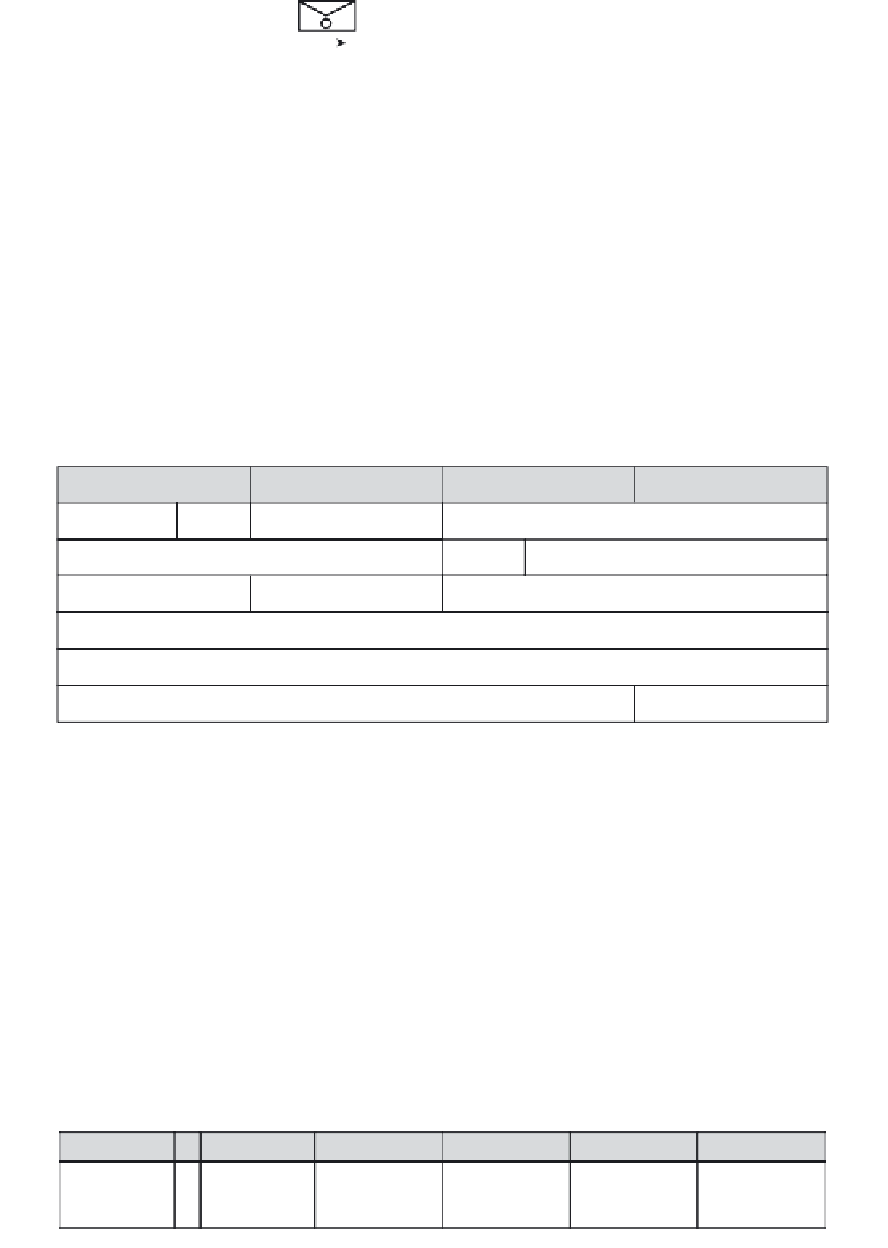
Figure 1-9 shows the structure of fields for the packet header. Fill in the missing field names.
Figure 1-9
Field Specification for the IP Header
Byte 1
Byte 2
Byte 3
Byte 4
Version
IHL
Type of Service
Packet Length
Identification
Flags
Fragment Offset
Time to Live
Protocol
Header Checksum
Source IP Address
Destination IP Address
Options
Padding
MAC Layer Frame Format Exercise
Figure 1-10 shows the two compatible version of Ethernet. Fill in the missing field names.
Figure 1-10
Field Specification for Ethernet Frames
Ethernet
Field Length in Bytes
8
6
6
2
46-1500
4
Destination
Address
Source
Address
Preamble
Type
Data
FCS
IEEE 802.3
Field Length in Bytes
7
1
S
O
F
6
6
2
46-1500
4
Destination
Address
Source
Address
802.2 Header
and Data
Preamble
Length
FCS


