Information Technology Reference
In-Depth Information
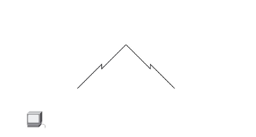
Figure 9-12
Topology Diagram for Lab 9-5 (Answer)
172.18.64.0/18
PC2
Fa0/0
HQ
S0/0/1
DCE
S0/0/0
209.165.202.128/30
209.165.202.132/30
S0/0/0
DCE
172.18.129.0/28
172.18.128.0/24
S0/0/1
S0/0/0
DCE
Fa0/0
Fa0/0
S0/0/1
B1
B2
209.165.202.136/30
PC1
PC3
Table 9-8
Addressing Table for Lab 9-5
Device
Interface
IP Address
Subnet Mask
Default Gateway
HQ
Fa0/0
172.18.64.1
255.255.192.0
—
S0/0/0
209.165.202.129
255.255.255.252
—
S0/0/1
209.165.202.133
255.255.255.252
—
BRANCH1
Fa0/0
172.18.129.1
255.255.255.240
—
S0/0/0
209.165.202.130
255.255.255.252
—
S0/0/1
209.165.202.137
255.255.255.252
—
BRANCH2
Fa0/0
172.18.128.1
255.255.255.0
—
S0/0/0
209.165.202.138
255.255.255.252
—
S0/0/1
209.165.202.134
255.255.255.252
—
PC1
NIC
172.18.129.14
172.18.129.1
255.255.255.240
PC2
NIC
172.18.100.100
172.18.64.1
255.255.192.0
PC3
NIC
172.18.128.10
172.18.128.1
255.255.255.0
Task 1: Cable, Erase, and Reload the Routers
Cable a network.
Step 1.
Cable a network that is similar to the one in the topology diagram in Figure 9-12.
Clear the configuration on each router.
Step 2.
Clear the configuration on each of the routers using the
erase startup-config
command
and then
reload
the routers. Answer
no
if asked to save changes.


