Geology Reference
In-Depth Information
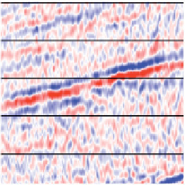
a)
b)
c)
Seismic Gather
Near Angle Stack
Far Angle Stack
Offset
Near traces
Far traces
5º 15º 35º
5-15º
15-35º
Figure 2.28
15°) stack. Note that the actual angles stacked
will depend on the available angle range and the choice as to number of stacks required (after Bacon
Angle stacks; (a) seismic gather, (b) near angle (5
-
15°) stack, (c) far angle (5
-
et al
AI
Rc
AI
Rc
V
p1
,
V
s1
,
ρ
1
V
p2
,
V
s2
,
ρ
2
Figure 2.29
Scaling: the key to seismic calibration; if the processor has been successful the amplitude is proportional to reflection coefficient
for a unique reflector. This is the key assumption in any inversion (
Chapter 9
) or quantitative amplitude interpretation.
The sub-stacks can be loaded to a structural inter-
pretation software package in just the same way as the
full stack. If the data processing is good the sub-stacks
will look similar to the full stack but amplitude
changes (for example, an increase from near to far
traces) will be immediately apparent when sub-stacks
are displayed side by side (
Fig. 2.28
). This gives the
interpreter a way to search through a 3D seismic
survey to look for anomalous AVO behaviour, which
can then be followed up by looking at CMP gathers.
As will be discussed, AVO differences are often made
more apparent by combining the data from partial
stacks using a weighting procedure (
Chapter 5
)
For the purpose of calibration of the angle stack to
a well-based AVO plot or indeed for seismic inversion
of individual stacks (
Chapter 9
), it can be considered
that each angle stack represents reflectivity at a par-
ticular (effective) angle. Theoretically, the effective
angle should be derived from the average of sin
2
θ
across the sub-stack, but in practice (especially since
the offset to angle transformation contains a degree of
uncertainty) it can usually be assumed to be the mid-
point of the range of angles included.
The goal of quantitative interpretation is to relate
changes in seismic amplitude to changes in rock prop-
erties. A key aspect of this is the scaling of the seismic
amplitude to the reflection coefficient (
Fig. 2.29
). This
is done principally through well ties (
Chapter 4
).
Correct scaling is particularly critical for seismic
inversion (
Chapter 9
), but problems with scaling can
seriously compromise all quantitative amplitude
interpretation.
22