Geology Reference
In-Depth Information
Offset (m)
a)
Velocity (m/s)
b)
Offset (m)
0
1000
2000
3000
4000
0
500
1500
1000
1500
2000
T
0
=2000ms
V
rms
=2000m/s
2000
2500
2500
3000
Figure 2.23
Reflection hyperbola.
3000
time increases with offset approximately according
to a hyperbolic relation (
Fig. 2.23
):
3500
s
T
0
+
x
2
V
rms
T
x
¼
,
ð
2
:
18
Þ
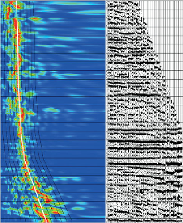
Figure 2.24
Velocity analysis; (a) semblance plot showing lines of
equal velocity (black) and stack coherency for each velocity shown
in colour (red
where T
x
is the time at offset x, T
0
is the time at zero
offset, and V
rms
is the RMS average velocity from the
surface to the reflector concerned. Given the assump-
tion that the overburden comprises a stack of layers
with velocity V and time thickness t, V
rms
is given by:
high coherency), (b) corrected gather using velocity
defined by velocity picks (white trend shown in (a)) (courtesy
Seismic Image Processing Ltd).
¼
x
2
V
i
V
rms
V
rms
T
0
+x
2
sin
2
θ ¼
,
ð
2
:
21
Þ
t
X
V
i
t
i
X
t
i
where T
0
is the zero offset travel time.
Figure 2.25
shows a moveout corrected gather with angle as a
coloured background. An alternative approach that
may be useful if velocity information is available
(for example sonic and check-shot data from a well)
is to calculate offset as a function of incidence angle,
using Snell
V
rms
¼
:
ð
2
:
19
Þ
In practice, stacking velocities are picked so that after
correcting for moveout the gather is flattened and
maximum coherence achieved (
Fig. 2.24
). These
stacking velocities are a first order approximation
for RMS velocities (see Al-Chalabi
s Law to follow the ray path through the
layers to the surface (
Fig. 2.26
). This requires a model
to be constructed for the near-surface where there is
likely to be no well data available, but it can give more
accurate angle estimates than those obtained from
stacking velocities. It is, however, not always clear
how to extrapolate well velocities away from a well,
as the velocities may show some combination of
stratigraphic conformance (if there are big differences
in lithology between layers) and increase with depth
due to compaction. It is certainly important to take
large changes in water depth into account. Ideally the
angle conversions obtained from seismic velocities
and from well velocities need to be checked against
one another and perhaps somehow combined; the
'
detailed discussion).
The interval velocity between two reflections at
s
T
2
V
rms2
T
1
V
rms1
V
i
¼
:
ð
2
:
20
Þ
T
2
T
1
This equation is usually applied to a time interval of at
least 200 ms to avoid instability arising from errors in
the RMS velocity estimates. Given the RMS velocity
down to a reflector and the interval velocity immedi-
ately above it, it can be shown that an estimate of the
incidence angle at offset x is given by:
20